Workflow Inputs
OpenStudio-HPXML requires a building description in an HPXML file format. HPXML is an open data standard for collecting and transferring home energy data. Using HPXML files reduces the complexity and effort for software developers to leverage the EnergyPlus simulation engine.
Using HPXML
HPXML is an flexible and extensible format, where nearly all elements in the schema are optional and custom elements can be included. Because of this, a stricter set of requirements for the HPXML file have been developed for purposes of running EnergyPlus simulations.
HPXML files submitted to OpenStudio-HPXML undergo a two step validation process:
Validation against the HPXML Schema
The HPXML XSD Schema can be found at
HPXMLtoOpenStudio/resources/hpxml_schema/HPXML.xsd. XSD Schemas are used to validate what elements/attributes/enumerations are available, data types for elements/attributes, the number/order of children elements, etc.
Validation using Schematron
The Schematron document for the EnergyPlus use case can be found at
HPXMLtoOpenStudio/resources/hpxml_schematron/EPvalidator.sch. Schematron is a rule-based validation language, expressed in XML using XPath expressions, for validating the presence or absence of inputs in XML files. As opposed to an XSD Schema, a Schematron document validates constraints and requirements based on conditionals and other logical statements. For example, if an element is specified with a particular value, the applicable enumerations of another element may change.
OpenStudio-HPXML automatically validates the HPXML file against both the XSD and Schematron documents and reports any validation errors, but software developers may find it beneficial to also integrate validation into their software.
Input Defaults
A large number of elements in the HPXML file are optional and can be defaulted. Default values, equations, and logic are described throughout this documentation.
For example, suppose a HPXML file has a refrigerator defined as follows:
<Refrigerator>
  <SystemIdentifier id='Refrigerator1'/>
</Refrigerator>
Default values would be used for the refrigerator energy use, location, and schedule:
<Refrigerator>
  <SystemIdentifier id='Refrigerator1'/>
  <Location dataSource='software'>conditioned space</Location>
  <RatedAnnualkWh dataSource='software'>691.0</RatedAnnualkWh>
  <PrimaryIndicator dataSource='software'>true</PrimaryIndicator>
  <extension>
    <UsageMultiplier dataSource='software'>1.0</UsageMultiplier>
    <WeekdayScheduleFractions dataSource='software'>0.040, 0.039, 0.038, 0.037, 0.036, 0.036, 0.038, 0.040, 0.041, 0.041, 0.040, 0.040, 0.042, 0.042, 0.042, 0.041, 0.044, 0.048, 0.050, 0.048, 0.047, 0.046, 0.044, 0.041</WeekdayScheduleFractions>
    <WeekendScheduleFractions dataSource='software'>0.040, 0.039, 0.038, 0.037, 0.036, 0.036, 0.038, 0.040, 0.041, 0.041, 0.040, 0.040, 0.042, 0.042, 0.042, 0.041, 0.044, 0.048, 0.050, 0.048, 0.047, 0.046, 0.044, 0.041</WeekendScheduleFractions>
    <MonthlyScheduleMultipliers dataSource='software'>0.837, 0.835, 1.084, 1.084, 1.084, 1.096, 1.096, 1.096, 1.096, 0.931, 0.925, 0.837</MonthlyScheduleMultipliers>
  </extension>
</Refrigerator>
These defaults will be reflected in the EnergyPlus simulation results.
Note
The OpenStudio-HPXML workflow generally treats missing elements differently than missing values.
For example, if there is no Refrigerator element defined, the simulation will proceed without refrigerator energy use.
On the other hand, if there is a Refrigerator element but with no values defined (i.e., no Location or RatedAnnualkWh), it is assumed that a refrigerator exists but its properties are unknown, so they will be defaulted in the model.
See HPXML Defaults for information on how default values can be inspected.
HPXML Software Info
High-level simulation inputs are entered in /HPXML/SoftwareInfo.
HPXML Simulation Control
EnergyPlus simulation controls are entered in /HPXML/SoftwareInfo/extension/SimulationControl.
Element
Type
Units
Constraints
Required
Default
Notes
Timestepinteger
minutes
Divisor of 60
No
60 (1 hour)
Timestep
BeginMonthinteger
>= 1, <= 12 [1]
No
1 (January)
Run period start date
BeginDayOfMonthinteger
>= 1, <= 31
No
1
Run period start date
EndMonthinteger
>= 1, <= 12
No
12 (December)
Run period end date
EndDayOfMonthinteger
>= 1, <= 31
No
31
Run period end date
CalendarYearinteger
> 1600 [2]
No
2007 (for TMY weather) [3]
Calendar year (for start day of week)
AdvancedResearchFeatureselement
No
<none>
Features used for advanced research modeling
To enable advanced research features, additional information is entered in /HPXML/SoftwareInfo/extension/SimulationControl/AdvancedResearchFeatures.
These features may require shorter timesteps, allow more sophisticated simulation control, and/or impact simulation runtime.
Element
Type
Units
Constraints
Required
Default
Notes
TemperatureCapacitanceMultiplierdouble
> 0
No
7.0 [4]
Multiplier on air heat capacitance [5]
OnOffThermostatDeadbandTemperaturedouble
F
> 0 [6]
No
Temperature difference between cut-in and cut-out temperature for HVAC operation [7]
HeatPumpBackupCapacityIncrementdouble
Btu/hr
> 0 [8]
No
Capacity increment of multi-stage heat pump backup systems [9]
GroundToAirHeatPumpModelTypestring
See [10]
No
standard
Ground-to-air heat pump system model type [11]
HPXML Emissions Scenarios
One or more emissions scenarios can be entered as an /HPXML/SoftwareInfo/extension/EmissionsScenarios/EmissionsScenario.
If not entered, emissions will not be calculated.
See Annual Outputs and Timeseries Outputs for descriptions of how the calculated emissions appear in the output files.
Electricity Emissions
For each scenario, electricity emissions factors must be entered as an /HPXML/SoftwareInfo/extension/EmissionsScenarios/EmissionsScenario/EmissionsFactor.
If an electricity schedule file is used, additional information can be entered in the /HPXML/SoftwareInfo/extension/EmissionsScenarios/EmissionsScenario/EmissionsFactor.
Element
Type
Units
Constraints
Required
Default
Notes
NumberofHeaderRowsinteger
#
>= 0
No
0
Number of header rows in the schedule file
ColumnNumberinteger
#
>= 1
No
1
Column number of the data in the schedule file
Fuel Emissions
For each scenario, fuel emissions factors can be optionally entered as an /HPXML/SoftwareInfo/extension/EmissionsScenarios/EmissionsScenario/EmissionsFactor.
Default Values
If EmissionsType is “CO2e”, “NOx” or “SO2” and a given fuel’s emissions factor is not entered, they will be defaulted as follows.
Fuel Type
CO2e [lb/MBtu]
NOx [lb/MBtu]
SO2 [lb/MBtu]
natural gas
147.3
0.0922
0.0006
propane
177.8
0.1421
0.0002
fuel oil
195.9
0.1300
0.0015
coal
–
–
–
wood
–
–
–
wood pellets
–
–
–
Default values in lb/MBtu (million Btu) are from ANSI/RESNET/ICC 301-2022 Addendum B and include both combustion and pre-combustion (e.g., methane leakage for natural gas) emissions.
If no default value is available, a warning will be issued.
HPXML Utility Bill Scenarios
One or more utility bill scenarios can be entered as an /HPXML/SoftwareInfo/extension/UtilityBillScenarios/UtilityBillScenario.
If not entered, utility bills will not be calculated.
Element
Type
Units
Constraints
Required
Default
Notes
Namestring
Yes
Name of the scenario (which shows up in the output file)
UtilityRateelement
No
Utility rate(s) for a given fuel type; multiple are allowed
PVCompensationelement
No
PV compensation information
See Utility Bill Outputs for a description of how the calculated utility bills appear in the output files.
Electricity Rates
For each scenario, electricity rates can be optionally entered as an /HPXML/SoftwareInfo/extension/UtilityBillScenarios/UtilityBillScenario/UtilityRate.
Electricity rates can be entered using Simple inputs or Detailed inputs.
Simple
For simple utility rate structures, inputs can be entered using a fixed charge and a marginal rate.
Detailed
For detailed utility rate structures, inputs can be entered using a tariff JSON file.
Element
Type
Units
Constraints
Required
Default
Notes
FuelTypestring
electricity
Yes
Fuel type
TariffFilePathstring
Yes
Path to tariff JSON file [20]
Fuel Rates
For each scenario, fuel rates can be optionally entered as an /HPXML/SoftwareInfo/extension/UtilityBillScenarios/UtilityBillScenario/UtilityRate.
PV Compensation
For each scenario, PV compensation information can be optionally entered in /HPXML/SoftwareInfo/extension/UtilityBillScenarios/UtilityBillScenario/PVCompensation.
Element
Type
Units
Constraints
Required
Default
Notes
CompensationType[NetMetering | FeedInTariff]element
No
NetMetering
PV compensation type
MonthlyGridConnectionFee[Units="$/kW" or Units="$"]/Valuedouble
No
0
PV monthly grid connection fee
Net-Metering
If the PV compensation type is net-metering, additional information can be entered in /HPXML/SoftwareInfo/extension/UtilityBillScenarios/UtilityBillScenario/PVCompensation/CompensationType/NetMetering.
Feed-in Tariff
If the PV compensation type is feed-in tariff, additional information can be entered in /HPXML/SoftwareInfo/extension/UtilityBillScenarios/UtilityBillScenario/PVCompensation/CompensationType/FeedInTariff.
Element
Type
Units
Constraints
Required
Default
Notes
FeedInTariffRatedouble
$/kWh
No
0.12
Feed-in tariff rate [29]
HPXML Electric Panel Calculations
To enable electric panel load calculations, one or more calculation types (e.g., 2023 NEC 220.83) can be entered in /HPXML/SoftwareInfo/extension/ElectricPanelCalculations/ServiceFeeders.
If not entered, electric panel loads will not be calculated.
These calculations are currently considered experimental research features.
Element
Type
Units
Constraints
Required
Default
Notes
Typestring
See [31]
Yes
Electric panel calculation vintage/method; multiple are allowed
See Electric Panel Outputs for descriptions of how calculated loads appear in the output files.
The electric panel baseline peak power is entered in /HPXML/Building/BuildingDetails/BuildingSummary/extension.
Element
Type
Units
Constraints
Required
Default
Notes
ElectricPanelBaselinePeakPowerdouble
W
> 0
See [32]
Used for meter-based load calculations
HPXML Building
OpenStudio-HPXML can be used to model either individual residential Dwelling Units or Whole SFA/MF Buildings.
In either case, each residential dwelling unit is entered as a /HPXML/Building.
Element
Type
Units
Constraints
Required
Default
Notes
BuildingIDid
Yes
Unique identifier
Dwelling Units
OpenStudio-HPXML can model individual residential dwelling units – either a single-family detached (SFD) building, or a single unit of a single-family attached (SFA) or multifamily (MF) building. This approach:
Is required/desired for certain applications (e.g., a Home Energy Score or an Energy Rating Index calculation).
Improves runtime speed by being able to simulate individual units in parallel (as opposed to simulating the entire building).
For these simulations:
Surfaces can be defined adjacent to generic SFA/MF spaces (e.g., “other housing unit” or “other multifamily buffer space”) with assumed temperature profiles (see HPXML Locations).
Various building components (e.g., ducts, water heaters, appliances) can be located in these SFA/MF spaces.
Shared systems (HVAC, water heating, mechanical ventilation, etc.) serving multiple dwelling units can be defined, in which these systems are approximated as individual systems with efficiency adjustments to estimate the energy use attributed to the unit.
Energy use attributed only to the dwelling unit is calculated.
Whole SFA/MF Buildings
Alternatively, OpenStudio-HPXML can model whole SFA/MF buildings in a single combined simulation.
Modeling a whole SFA/MF building is defined in /HPXML/SoftwareInfo/extension.
Element
Type
Units
Constraints
Required
Default
Notes
WholeSFAorMFBuildingSimulationboolean
No
false
Whether to run an individual dwelling unit or whole building for SFA/MF [33]
For these simulations:
An HPXML file with multiple
Buildingelements is used, where eachBuildingrepresents an individual dwelling unit.Unit multipliers (using the
NumberofUnitselement; see HPXML Building Construction) can be specified to model unique dwelling units, rather than all dwelling units, reducing simulation runtime.Adjacent SFA/MF common spaces are still modeled using assumed temperature profiles, not as separate thermal zones. (This may change in the future.)
Shared systems are still modeled as individual systems, not shared systems connected to multiple dwelling unit. (This may change in the future.)
Energy use for the entire building is calculated; you cannot get energy use for individual dwelling units. (This may change in the future.)
Notes/caveats about this approach:
Some inputs (e.g., EPW location or ground conductivity) cannot vary across
Buildingelements.HPXML Batteries and HPXML Vehicles are not currently supported.
HPXML Utility Bill Scenarios using detailed Electricity Rates are not supported.
HPXML Building Site
Building site information can be entered in /HPXML/Building/Site.
Element
Type
Units
Constraints
Required
Default
Notes
SiteIDid
Yes
Unique identifier
Address/CityMunicipalitystring
No
See [34]
Address city/municipality
Address/StateCodestring
No
See [35]
Address state/territory
Address/ZipCodestring
See [36]
See [37]
Address ZIP Code
GeoLocation/Latitudedouble
deg
>= -90, <= 90
No
See [38]
Site latitude (negative for southern hemisphere)
GeoLocation/Longitudedouble
deg
>= -180, <= 180
No
See [39]
Site longitude (negative for western hemisphere)
Elevationdouble
ft
No
See [40]
Site elevation
TimeZone/UTCOffsetdouble
>= -12, <= 14
No
See [41]
Difference in decimal hours between the home’s time zone and UTC
TimeZone/DSTObservedboolean
No
true
Daylight saving time observed?
If daylight saving time is observed, additional information can be specified in /HPXML/Building/Site/TimeZone/extension.
Element
Type
Units
Constraints
Required
Default
Notes
DSTBeginMonthandDSTBeginDayOfMonthinteger
>= 1, <= 12 and >= 1, <= 31
No
EPW else 3/12 (March 12) [42]
Start date
DSTEndMonthandDSTEndDayOfMonthinteger
>= 1, <= 12 and >= 1, <= 31
No
EPW else 11/5 (November 5)
End date
HPXML Building Summary
High-level building summary information is entered in /HPXML/Building/BuildingDetails/BuildingSummary.
HPXML Site
Site information is entered in /HPXML/Building/BuildingDetails/BuildingSummary/Site.
Element
Type
Units
Constraints
Required
Default
Notes
SiteTypestring
See [43]
No
suburban
Terrain type for infiltration model
ShieldingofHomestring
See [44]
No
See [45]
Presence of nearby buildings, trees, obstructions for infiltration model
Soil/SoilTypestring
See [46]
No
unknown
Soil type
Soil/MoistureTypestring
See [47]
No
mixed
Soil moisture type
Soil/Conductivitydouble
Btu/hr-ft-F
> 0
No
See [48]
Soil thermal conductivity
Soil/extension/Diffusivitydouble
ft2/hr
> 0
No
See [49]
Soil thermal diffusivity
extension/Neighborselement
No
<none>
Presence of neighboring buildings for solar shading
Note
Soil conductivity is used for foundation heat transfer and ground source heat pumps. Soil diffusivity is used for ground source heat pumps.
HPXML Neighbor Buildings
For each neighboring building defined, additional information is entered in a extension/Neighbors/NeighborBuilding.
Element
Type
Units
Constraints
Required
Default
Notes
AzimuthorOrientationinteger or string
deg or direction
>= 0, <= 359 or See [50]
Yes
Direction of neighbors (clockwise from North)
Distancedouble
ft
> 0
Yes
Distance of neighbor from the dwelling unit
Heightdouble
ft
> 0
No
See [51]
Height of neighbor
HPXML Building Occupancy
Building occupancy is entered in /HPXML/Building/BuildingDetails/BuildingSummary/BuildingOccupancy.
Element
Type
Units
Constraints
Required
Default
Notes
NumberofResidentsdouble
>= 0
No
See [52]
Number of occupants
extension/WeekdayScheduleFractionsarray
No
See [53]
24 comma-separated weekday fractions
extension/WeekendScheduleFractionsarray
No
24 comma-separated weekend fractions
extension/MonthlyScheduleMultipliersarray
No
See [54]
12 comma-separated monthly multipliers
extension/GeneralWaterUseUsageMultiplierdouble
>= 0
No
1.0
Multiplier on general water use internal gains [55]
extension/GeneralWaterUseWeekdayScheduleFractionsarray
No
See [56]
24 comma-separated weekday fractions
extension/GeneralWaterUseWeekendScheduleFractionsarray
No
24 comma-separated weekend fractions
extension/GeneralWaterUseMonthlyScheduleMultipliersarray
No
See [57]
12 comma-separated monthly multipliers
HPXML Building Construction
Building construction is entered in /HPXML/Building/BuildingDetails/BuildingSummary/BuildingConstruction.
Element
Type
Units
Constraints
Required
Default
Notes
YearBuiltinteger
> 0
See [58]
Year built of the dwelling unit
ResidentialFacilityTypestring
See [59]
Yes
Type of dwelling unit
UnitHeightAboveGradedouble
ft
No
See [60]
Height of the unit’s lowest conditioned floor above grade [61]
NumberofUnitsinteger
>= 1
No
1
Unit multiplier [62]
NumberofConditionedFloorsdouble
> 0
Yes
Number of conditioned floors (including a conditioned basement; excluding a conditioned crawlspace)
NumberofConditionedFloorsAboveGradedouble
> 0, <= NumberofConditionedFloors
Yes
Number of conditioned floors above grade (including a walkout basement)
AverageCeilingHeightdouble
ft
> 0
No
See [63]
Floor to ceiling height within conditioned space
NumberofBedroomsinteger
>= 0
Yes
Number of bedrooms
NumberofBathroomsinteger
> 0
No
See [64]
Number of bathrooms
ConditionedFloorAreadouble
ft2
> 0
Yes
Floor area within conditioned space boundary (excluding conditioned crawlspace floor area)
ConditionedBuildingVolumedouble
ft3
> 0
No
See [65]
Volume within conditioned space boundary (including a conditioned basement/crawlspace)
HPXML Schedules
Schedules for a variety of building features can be defined using:
It is allowed to use simple, detailed, and defaulted values in the same HPXML file.
Simple Schedule Inputs
Simple schedule inputs are available as weekday/weekend fractions and monthly multipliers for a variety of building characteristics.
For example, see the WeekdayScheduleFractions, WeekendScheduleFractions, and MonthlyScheduleMultipliers inputs for HPXML Building Occupancy.
Detailed Schedule Inputs
Detailed schedule inputs allow schedule values for every hour or timestep of the simulation. They can be used to reflect real-world or stochastic occupancy.
Detailed schedule inputs are provided via one or more CSV file that should be referenced in the HPXML file as /HPXML/Building/BuildingDetails/BuildingSummary/extension/SchedulesFilePath elements.
The column names available in the schedule CSV files are:
Column Name
Units
Notes
Can Be Stochastically Generated [66]
occupantsfrac
Occupant heat gain schedule.
Yes
lighting_interiorfrac
Interior lighting energy use schedule.
Yes
lighting_exteriorfrac
Exterior lighting energy use schedule.
No
lighting_garagefrac
Garage lighting energy use schedule.
Yes
lighting_exterior_holidayfrac
Exterior holiday lighting energy use schedule.
No
cooking_rangefrac
Cooking range & oven energy use schedule.
Yes
refrigeratorfrac
Primary refrigerator energy use schedule.
No
extra_refrigeratorfrac
Non-primary refrigerator energy use schedule.
No
freezerfrac
Freezer energy use schedule.
No
dishwasherfrac
Dishwasher energy use schedule.
Yes
clothes_washerfrac
Clothes washer energy use schedule.
Yes
clothes_dryerfrac
Clothes dryer energy use schedule.
Yes
ceiling_fanfrac
Ceiling fan energy use schedule.
Yes
plug_loads_otherfrac
Other plug load energy use schedule.
Yes
plug_loads_tvfrac
Television plug load energy use schedule.
Yes
plug_loads_vehiclefrac
Electric vehicle plug load energy use schedule. [67]
No
plug_loads_well_pumpfrac
Well pump plug load energy use schedule.
No
fuel_loads_grillfrac
Grill fuel load energy use schedule.
No
fuel_loads_lightingfrac
Lighting fuel load energy use schedule.
No
fuel_loads_fireplacefrac
Fireplace fuel load energy use schedule.
No
pool_pumpfrac
Pool pump energy use schedule.
No
pool_heaterfrac
Pool heater energy use schedule.
No
permanent_spa_pumpfrac
Permanent spa pump energy use schedule.
No
permanent_spa_heaterfrac
Permanent spa heater energy use schedule.
No
hot_water_dishwasherfrac
Dishwasher hot water use schedule.
Yes
hot_water_clothes_washerfrac
Clothes washer hot water use schedule.
Yes
hot_water_fixturesfrac
Fixtures (sinks, showers, baths) hot water use schedule.
Yes
hot_water_recirculation_pumpfrac
Hot water recirculation pump schedule.
No
general_water_usefrac
General water use internal gains.
No
heating_setpointF
Thermostat heating setpoint schedule.
No
cooling_setpointF
Thermostat cooling setpoint schedule.
No
hvac_maximum_power_ratiofrac
Variable speed system maximum power ratio schedule. [68]
No
water_heater_setpointF
Water heater setpoint schedule.
No
water_heater_operating_mode0/1
Heat pump water heater operating mode schedule. 0=hybrid/auto, 1=heat pump only.
No
battery-1 to 1
Battery availability schedule. Positive for charging, negative for discharging.
No
electric_vehicle-1 to 1
Electric vehicle schedule. Positive for charging, negative for discharging. [69]
Yes
Columns with units of frac must be normalized to MAX=1; that is, these schedules only define when energy is used, not how much energy is used.
In other words, the amount of energy or hot water used in each simulation timestep is essentially the schedule value divided by the sum of all schedule values in the column, multiplied by the annual energy or hot water use.
Example schedule CSV files are provided in the HPXMLtoOpenStudio/resources/schedule_files directory.
The schedule file must have a full year of data even if the simulation is not an entire year. Frequency of schedule values do not need to match the simulation timestep. For example, hourly schedules can be used with a 10-minute simulation timestep, or 10-minute schedules can be used with an hourly simulation timestep.
Warning
For simulations with daylight saving enabled (which is the default), EnergyPlus will skip forward an hour in the CSV on the “spring forward” day and repeat an hour on the “fall back” day.
Default Schedules
If neither simple nor detailed inputs are provided, then schedules are defaulted.
Default schedules are typically smooth, averaged schedules.
These default schedules (and data sources) are described in the table below (e.g., see “occupants” rows for the default occupant heat gain schedule).
They can also be found at HPXMLtoOpenStudio/resources/data/default_schedules.csv.
Schedule Name |
Element |
Values |
Data Source |
|---|---|---|---|
occupants |
WeekdayScheduleFractions |
0.035, 0.035, 0.035, 0.035, 0.035, 0.059, 0.082, 0.055, 0.027, 0.014, 0.014, 0.014, 0.014, 0.014, 0.019, 0.027, 0.041, 0.055, 0.068, 0.082, 0.082, 0.070, 0.053, 0.035 |
Table C.3(5) of ANSI/RESNET/ICC 301-2022 Addendum C |
occupants |
WeekendScheduleFractions |
0.035, 0.035, 0.035, 0.035, 0.035, 0.059, 0.082, 0.055, 0.027, 0.014, 0.014, 0.014, 0.014, 0.014, 0.019, 0.027, 0.041, 0.055, 0.068, 0.082, 0.082, 0.070, 0.053, 0.035 |
Table C.3(5) of ANSI/RESNET/ICC 301-2022 Addendum C |
occupants |
MonthlyScheduleMultipliers |
1.0, 1.0, 1.0, 1.0, 1.0, 1.0, 1.0, 1.0, 1.0, 1.0, 1.0, 1.0 |
|
general_water_use |
GeneralWaterUseWeekdayScheduleFractions |
0.023, 0.021, 0.021, 0.025, 0.027, 0.038, 0.044, 0.039, 0.037, 0.037, 0.034, 0.035, 0.035, 0.035, 0.039, 0.043, 0.051, 0.064, 0.065, 0.072, 0.073, 0.063, 0.045, 0.034 |
Table C.3(5) of ANSI/RESNET/ICC 301-2022 Addendum C |
general_water_use |
GeneralWaterUseWeekendScheduleFractions |
0.023, 0.021, 0.021, 0.025, 0.027, 0.038, 0.044, 0.039, 0.037, 0.037, 0.034, 0.035, 0.035, 0.035, 0.039, 0.043, 0.051, 0.064, 0.065, 0.072, 0.073, 0.063, 0.045, 0.034 |
Table C.3(5) of ANSI/RESNET/ICC 301-2022 Addendum C |
general_water_use |
GeneralWaterUseMonthlyScheduleMultipliers |
1.0, 1.0, 1.0, 1.0, 1.0, 1.0, 1.0, 1.0, 1.0, 1.0, 1.0, 1.0 |
|
lighting_interior |
InteriorWeekdayScheduleFractions |
0.012, 0.010, 0.010, 0.010, 0.011, 0.018, 0.030, 0.038, 0.041, 0.041, 0.039, 0.037, 0.036, 0.035, 0.037, 0.041, 0.050, 0.065, 0.086, 0.106, 0.110, 0.079, 0.040, 0.018 |
Table C.3(3) of ANSI/RESNET/ICC 301-2022 Addendum C |
lighting_interior |
InteriorWeekendScheduleFractions |
0.012, 0.010, 0.010, 0.010, 0.011, 0.018, 0.030, 0.038, 0.041, 0.041, 0.039, 0.037, 0.036, 0.035, 0.037, 0.041, 0.050, 0.065, 0.086, 0.106, 0.110, 0.079, 0.040, 0.018 |
Table C.3(3) of ANSI/RESNET/ICC 301-2022 Addendum C |
lighting_interior |
InteriorMonthlyScheduleMultipliers |
1.19, 1.11, 1.02, 0.93, 0.84, 0.80, 0.82, 0.88, 0.98, 1.07, 1.16, 1.20 |
Table C.3(4) of ANSI/RESNET/ICC 301-2022 Addendum C |
lighting_exterior |
ExteriorWeekdayScheduleFractions |
0.040, 0.037, 0.037, 0.035, 0.035, 0.039, 0.044, 0.041, 0.031, 0.025, 0.024, 0.024, 0.025, 0.028, 0.030, 0.035, 0.044, 0.056, 0.064, 0.068, 0.070, 0.065, 0.056, 0.047 |
Table C.3(3) of ANSI/RESNET/ICC 301-2022 Addendum C |
lighting_exterior |
ExteriorWeekendScheduleFractions |
0.040, 0.037, 0.037, 0.035, 0.035, 0.039, 0.044, 0.041, 0.031, 0.025, 0.024, 0.024, 0.025, 0.028, 0.030, 0.035, 0.044, 0.056, 0.064, 0.068, 0.070, 0.065, 0.056, 0.047 |
Table C.3(3) of ANSI/RESNET/ICC 301-2022 Addendum C |
lighting_exterior |
ExteriorMonthlyScheduleMultipliers |
1.19, 1.11, 1.02, 0.93, 0.84, 0.80, 0.82, 0.88, 0.98, 1.07, 1.16, 1.20 |
Table C.3(4) of ANSI/RESNET/ICC 301-2022 Addendum C |
lighting_garage |
GarageWeekdayScheduleFractions |
0.023, 0.019, 0.015, 0.017, 0.021, 0.031, 0.042, 0.041, 0.034, 0.029, 0.027, 0.025, 0.021, 0.021, 0.021, 0.026, 0.031, 0.044, 0.084, 0.117, 0.113, 0.096, 0.063, 0.039 |
Table C.3(3) of ANSI/RESNET/ICC 301-2022 Addendum C |
lighting_garage |
GarageWeekendScheduleFractions |
0.023, 0.019, 0.015, 0.017, 0.021, 0.031, 0.042, 0.041, 0.034, 0.029, 0.027, 0.025, 0.021, 0.021, 0.021, 0.026, 0.031, 0.044, 0.084, 0.117, 0.113, 0.096, 0.063, 0.039 |
Table C.3(3) of ANSI/RESNET/ICC 301-2022 Addendum C |
lighting_garage |
GarageMonthlyScheduleMultipliers |
1.19, 1.11, 1.02, 0.93, 0.84, 0.80, 0.82, 0.88, 0.98, 1.07, 1.16, 1.20 |
Table C.3(4) of ANSI/RESNET/ICC 301-2022 Addendum C |
lighting_exterior_holiday |
WeekdayScheduleFractions |
0.0, 0.0, 0.0, 0.0, 0.0, 0.0, 0.0, 0.0, 0.0, 0.0, 0.0, 0.0, 0.0, 0.0, 0.0, 0.0, 0.008, 0.098, 0.168, 0.194, 0.284, 0.192, 0.037, 0.019 |
|
lighting_exterior_holiday |
WeekendScheduleFractions |
0.0, 0.0, 0.0, 0.0, 0.0, 0.0, 0.0, 0.0, 0.0, 0.0, 0.0, 0.0, 0.0, 0.0, 0.0, 0.0, 0.008, 0.098, 0.168, 0.194, 0.284, 0.192, 0.037, 0.019 |
|
cooking_range |
WeekdayScheduleFractions |
0.008, 0.008, 0.008, 0.008, 0.008, 0.015, 0.023, 0.039, 0.046, 0.046, 0.046, 0.054, 0.062, 0.046, 0.039, 0.054, 0.076, 0.134, 0.114, 0.058, 0.039, 0.031, 0.023, 0.015 |
Table C.3(1) of ANSI/RESNET/ICC 301-2022 Addendum C |
cooking_range |
WeekendScheduleFractions |
0.008, 0.008, 0.008, 0.008, 0.008, 0.015, 0.023, 0.039, 0.046, 0.046, 0.046, 0.054, 0.062, 0.046, 0.039, 0.054, 0.076, 0.134, 0.114, 0.058, 0.039, 0.031, 0.023, 0.015 |
Table C.3(1) of ANSI/RESNET/ICC 301-2022 Addendum C |
cooking_range |
MonthlyScheduleMultipliers |
1.0, 1.0, 1.0, 1.0, 1.0, 1.0, 1.0, 1.0, 1.0, 1.0, 1.0, 1.0 |
|
refrigerator |
WeekdayScheduleFractions |
0.040, 0.039, 0.038, 0.037, 0.036, 0.036, 0.038, 0.040, 0.041, 0.041, 0.040, 0.040, 0.042, 0.042, 0.042, 0.041, 0.044, 0.048, 0.050, 0.048, 0.047, 0.046, 0.044, 0.041 |
Figure 16 of the 2010 BAHSP |
refrigerator |
WeekendScheduleFractions |
0.040, 0.039, 0.038, 0.037, 0.036, 0.036, 0.038, 0.040, 0.041, 0.041, 0.040, 0.040, 0.042, 0.042, 0.042, 0.041, 0.044, 0.048, 0.050, 0.048, 0.047, 0.046, 0.044, 0.041 |
Figure 16 of the 2010 BAHSP |
refrigerator |
MonthlyScheduleMultipliers |
0.837, 0.835, 1.084, 1.084, 1.084, 1.096, 1.096, 1.096, 1.096, 0.931, 0.925, 0.837 |
Figure 24 of the 2010 BAHSP |
refrigerator |
ConstantScheduleCoefficients |
-0.487, -0.340, -0.370, -0.361, -0.515, -0.684, -0.471, -0.159, -0.079, -0.417, -0.411, -0.386, -0.240, -0.314, -0.160, -0.121, -0.469, -0.412, -0.091, 0.077, -0.118, -0.247, -0.445, -0.544 |
Table C.3(2) of ANSI/RESNET/ICC 301-2022 Addendum C |
refrigerator |
TemperatureScheduleCoefficients |
0.019, 0.016, 0.017, 0.016, 0.018, 0.021, 0.019, 0.015, 0.015, 0.019, 0.018, 0.018, 0.016, 0.017, 0.015, 0.015, 0.020, 0.020, 0.017, 0.014, 0.016, 0.017, 0.019, 0.020 |
Table C.3(2) of ANSI/RESNET/ICC 301-2022 Addendum C |
extra_refrigerator |
WeekdayScheduleFractions |
0.040, 0.039, 0.038, 0.037, 0.036, 0.036, 0.038, 0.040, 0.041, 0.041, 0.040, 0.040, 0.042, 0.042, 0.042, 0.041, 0.044, 0.048, 0.050, 0.048, 0.047, 0.046, 0.044, 0.041 |
Figure 16 of the 2010 BAHSP |
extra_refrigerator |
WeekendScheduleFractions |
0.040, 0.039, 0.038, 0.037, 0.036, 0.036, 0.038, 0.040, 0.041, 0.041, 0.040, 0.040, 0.042, 0.042, 0.042, 0.041, 0.044, 0.048, 0.050, 0.048, 0.047, 0.046, 0.044, 0.041 |
Figure 16 of the 2010 BAHSP |
extra_refrigerator |
MonthlyScheduleMultipliers |
0.837, 0.835, 1.084, 1.084, 1.084, 1.096, 1.096, 1.096, 1.096, 0.931, 0.925, 0.837 |
Figure 24 of the 2010 BAHSP |
extra_refrigerator |
ConstantScheduleCoefficients |
-0.487, -0.340, -0.370, -0.361, -0.515, -0.684, -0.471, -0.159, -0.079, -0.417, -0.411, -0.386, -0.240, -0.314, -0.160, -0.121, -0.469, -0.412, -0.091, -0.077, -0.118, -0.247, -0.445, -0.544 |
Table C.3(2) of ANSI/RESNET/ICC 301-2022 Addendum C |
extra_refrigerator |
TemperatureScheduleCoefficients |
0.019, 0.016, 0.017, 0.016, 0.018, 0.021, 0.019, 0.015, 0.015, 0.019, 0.018, 0.018, 0.016, 0.017, 0.015, 0.015, 0.020, 0.020, 0.017, 0.014, 0.016, 0.017, 0.019, 0.020 |
Table C.3(2) of ANSI/RESNET/ICC 301-2022 Addendum C |
freezer |
WeekdayScheduleFractions |
0.040, 0.039, 0.038, 0.037, 0.036, 0.036, 0.038, 0.040, 0.041, 0.041, 0.040, 0.040, 0.042, 0.042, 0.042, 0.041, 0.044, 0.048, 0.050, 0.048, 0.047, 0.046, 0.044, 0.041 |
Figure 16 of the 2010 BAHSP |
freezer |
WeekendScheduleFractions |
0.040, 0.039, 0.038, 0.037, 0.036, 0.036, 0.038, 0.040, 0.041, 0.041, 0.040, 0.040, 0.042, 0.042, 0.042, 0.041, 0.044, 0.048, 0.050, 0.048, 0.047, 0.046, 0.044, 0.041 |
Figure 16 of the 2010 BAHSP |
freezer |
MonthlyScheduleMultipliers |
0.837, 0.835, 1.084, 1.084, 1.084, 1.096, 1.096, 1.096, 1.096, 0.931, 0.925, 0.837 |
Figure 24 of the 2010 BAHSP |
dishwasher |
WeekdayScheduleFractions |
0.015, 0.007, 0.005, 0.003, 0.003, 0.010, 0.020, 0.031, 0.058, 0.065, 0.056, 0.048, 0.042, 0.046, 0.036, 0.038, 0.038, 0.049, 0.087, 0.111, 0.090, 0.067, 0.044, 0.031 |
Table C.3(1) of ANSI/RESNET/ICC 301-2022 Addendum C |
dishwasher |
WeekendScheduleFractions |
0.015, 0.007, 0.005, 0.003, 0.003, 0.010, 0.020, 0.031, 0.058, 0.065, 0.056, 0.048, 0.042, 0.046, 0.036, 0.038, 0.038, 0.049, 0.087, 0.111, 0.090, 0.067, 0.044, 0.031 |
Table C.3(1) of ANSI/RESNET/ICC 301-2022 Addendum C |
dishwasher |
MonthlyScheduleMultipliers |
1.0, 1.0, 1.0, 1.0, 1.0, 1.0, 1.0, 1.0, 1.0, 1.0, 1.0, 1.0 |
|
clothes_washer |
WeekdayScheduleFractions |
0.009, 0.007, 0.004, 0.004, 0.007, 0.011, 0.022, 0.049, 0.073, 0.086, 0.084, 0.075, 0.067, 0.060, 0.049, 0.051, 0.050, 0.049, 0.049, 0.049, 0.049, 0.047, 0.032, 0.017 |
Table C.3(1) of ANSI/RESNET/ICC 301-2022 Addendum C |
clothes_washer |
WeekendScheduleFractions |
0.009, 0.007, 0.004, 0.004, 0.007, 0.011, 0.022, 0.049, 0.073, 0.086, 0.084, 0.075, 0.067, 0.060, 0.049, 0.051, 0.050, 0.049, 0.049, 0.049, 0.049, 0.047, 0.032, 0.017 |
Table C.3(1) of ANSI/RESNET/ICC 301-2022 Addendum C |
clothes_washer |
MonthlyScheduleMultipliers |
1.0, 1.0, 1.0, 1.0, 1.0, 1.0, 1.0, 1.0, 1.0, 1.0, 1.0, 1.0 |
|
clothes_dryer |
WeekdayScheduleFractions |
0.010, 0.006, 0.004, 0.002, 0.004, 0.006, 0.016, 0.032, 0.048, 0.068, 0.078, 0.081, 0.074, 0.067, 0.058, 0.061, 0.055, 0.054, 0.051, 0.051, 0.052, 0.054, 0.044, 0.024 |
Table C.3(1) of ANSI/RESNET/ICC 301-2022 Addendum C |
clothes_dryer |
WeekendScheduleFractions |
0.010, 0.006, 0.004, 0.002, 0.004, 0.006, 0.016, 0.032, 0.048, 0.068, 0.078, 0.081, 0.074, 0.067, 0.058, 0.061, 0.055, 0.054, 0.051, 0.051, 0.052, 0.054, 0.044, 0.024 |
Table C.3(1) of ANSI/RESNET/ICC 301-2022 Addendum C |
clothes_dryer |
MonthlyScheduleMultipliers |
1.0, 1.0, 1.0, 1.0, 1.0, 1.0, 1.0, 1.0, 1.0, 1.0, 1.0, 1.0 |
|
ceiling_fan |
WeekdayScheduleFractions |
0.057, 0.057, 0.057, 0.057, 0.057, 0.057, 0.057, 0.024, 0.024, 0.024, 0.024, 0.024, 0.024, 0.024, 0.024, 0.024, 0.024, 0.024, 0.052, 0.057, 0.057, 0.057, 0.057, 0.057 |
Table C.3(5) of ANSI/RESNET/ICC 301-2022 Addendum C |
ceiling_fan |
WeekendScheduleFractions |
0.057, 0.057, 0.057, 0.057, 0.057, 0.057, 0.057, 0.024, 0.024, 0.024, 0.024, 0.024, 0.024, 0.024, 0.024, 0.024, 0.024, 0.024, 0.052, 0.057, 0.057, 0.057, 0.057, 0.057 |
Table C.3(5) of ANSI/RESNET/ICC 301-2022 Addendum C |
plug_loads_other |
WeekdayScheduleFractions |
0.036, 0.036, 0.036, 0.036, 0.036, 0.036, 0.038, 0.041, 0.042, 0.042, 0.042, 0.042, 0.042, 0.042, 0.042, 0.044, 0.047, 0.050, 0.051, 0.050, 0.048, 0.044, 0.040, 0.037 |
Table C.3(1) of ANSI/RESNET/ICC 301-2022 Addendum C |
plug_loads_other |
WeekendScheduleFractions |
0.036, 0.036, 0.036, 0.036, 0.036, 0.036, 0.038, 0.041, 0.042, 0.042, 0.042, 0.042, 0.042, 0.042, 0.042, 0.044, 0.047, 0.050, 0.051, 0.050, 0.048, 0.044, 0.040, 0.037 |
Table C.3(1) of ANSI/RESNET/ICC 301-2022 Addendum C |
plug_loads_other |
MonthlyScheduleMultipliers |
1.0, 1.0, 1.0, 1.0, 1.0, 1.0, 1.0, 1.0, 1.0, 1.0, 1.0, 1.0 |
|
plug_loads_vehicle |
WeekdayScheduleFractions |
0.053, 0.042, 0.034, 0.027, 0.026, 0.022, 0.017, 0.014, 0.012, 0.011, 0.011, 0.013, 0.018, 0.022, 0.026, 0.037, 0.054, 0.074, 0.088, 0.089, 0.086, 0.083, 0.076, 0.065 |
|
plug_loads_vehicle |
WeekendScheduleFractions |
0.055, 0.045, 0.036, 0.03, 0.028, 0.024, 0.019, 0.016, 0.014, 0.013, 0.014, 0.016, 0.021, 0.028, 0.035, 0.044, 0.056, 0.069, 0.077, 0.08, 0.078, 0.073, 0.067, 0.06 |
|
plug_loads_vehicle |
MonthlyScheduleMultipliers |
1.128, 1.1, 1.037, 0.984, 0.948, 0.932, 0.931, 0.93, 0.932, 0.969, 1.017, 1.096 |
|
plug_loads_tv |
WeekdayScheduleFractions |
0.014, 0.007, 0.004, 0.003, 0.004, 0.006, 0.010, 0.015, 0.020, 0.025, 0.028, 0.031, 0.033, 0.038, 0.042, 0.046, 0.054, 0.062, 0.080, 0.110, 0.132, 0.125, 0.077, 0.034 |
Table C.3(1) of ANSI/RESNET/ICC 301-2022 Addendum C |
plug_loads_tv |
WeekendScheduleFractions |
0.014, 0.007, 0.004, 0.003, 0.004, 0.006, 0.010, 0.015, 0.020, 0.025, 0.028, 0.031, 0.033, 0.038, 0.042, 0.046, 0.054, 0.062, 0.080, 0.110, 0.132, 0.125, 0.077, 0.034 |
Table C.3(1) of ANSI/RESNET/ICC 301-2022 Addendum C |
plug_loads_tv |
MonthlyScheduleMultipliers |
1.0, 1.0, 1.0, 1.0, 1.0, 1.0, 1.0, 1.0, 1.0, 1.0, 1.0, 1.0 |
|
plug_loads_well_pump |
WeekdayScheduleFractions |
0.044, 0.023, 0.019, 0.015, 0.016, 0.018, 0.026, 0.033, 0.033, 0.032, 0.033, 0.033, 0.032, 0.032, 0.032, 0.033, 0.045, 0.057, 0.066, 0.076, 0.081, 0.086, 0.075, 0.065 |
Figure 23 of the 2010 BAHSP |
plug_loads_well_pump |
WeekendScheduleFractions |
0.044, 0.023, 0.019, 0.015, 0.016, 0.018, 0.026, 0.033, 0.033, 0.032, 0.033, 0.033, 0.032, 0.032, 0.032, 0.033, 0.045, 0.057, 0.066, 0.076, 0.081, 0.086, 0.075, 0.065 |
Figure 23 of the 2010 BAHSP |
plug_loads_well_pump |
MonthlyScheduleMultipliers |
1.0, 1.0, 1.0, 1.0, 1.0, 1.0, 1.0, 1.0, 1.0, 1.0, 1.0, 1.0 |
|
fuel_loads_grill |
WeekdayScheduleFractions |
0.004, 0.001, 0.001, 0.002, 0.007, 0.012, 0.029, 0.046, 0.044, 0.041, 0.044, 0.046, 0.042, 0.038, 0.049, 0.059, 0.110, 0.161, 0.115, 0.070, 0.044, 0.019, 0.013, 0.007 |
Figure 23 of the 2010 BAHSP |
fuel_loads_grill |
WeekendScheduleFractions |
0.004, 0.001, 0.001, 0.002, 0.007, 0.012, 0.029, 0.046, 0.044, 0.041, 0.044, 0.046, 0.042, 0.038, 0.049, 0.059, 0.110, 0.161, 0.115, 0.070, 0.044, 0.019, 0.013, 0.007 |
Figure 23 of the 2010 BAHSP |
fuel_loads_grill |
MonthlyScheduleMultipliers |
1.0, 1.0, 1.0, 1.0, 1.0, 1.0, 1.0, 1.0, 1.0, 1.0, 1.0, 1.0 |
|
fuel_loads_lighting |
WeekdayScheduleFractions |
0.044, 0.023, 0.019, 0.015, 0.016, 0.018, 0.026, 0.033, 0.033, 0.032, 0.033, 0.033, 0.032, 0.032, 0.032, 0.033, 0.045, 0.057, 0.066, 0.076, 0.081, 0.086, 0.075, 0.065 |
Figure 23 of the 2010 BAHSP |
fuel_loads_lighting |
WeekendScheduleFractions |
0.044, 0.023, 0.019, 0.015, 0.016, 0.018, 0.026, 0.033, 0.033, 0.032, 0.033, 0.033, 0.032, 0.032, 0.032, 0.033, 0.045, 0.057, 0.066, 0.076, 0.081, 0.086, 0.075, 0.065 |
Figure 23 of the 2010 BAHSP |
fuel_loads_lighting |
MonthlyScheduleMultipliers |
1.0, 1.0, 1.0, 1.0, 1.0, 1.0, 1.0, 1.0, 1.0, 1.0, 1.0, 1.0 |
|
fuel_loads_fireplace |
WeekdayScheduleFractions |
0.044, 0.023, 0.019, 0.015, 0.016, 0.018, 0.026, 0.033, 0.033, 0.032, 0.033, 0.033, 0.032, 0.032, 0.032, 0.033, 0.045, 0.057, 0.066, 0.076, 0.081, 0.086, 0.075, 0.065 |
Figure 23 of the 2010 BAHSP |
fuel_loads_fireplace |
WeekendScheduleFractions |
0.044, 0.023, 0.019, 0.015, 0.016, 0.018, 0.026, 0.033, 0.033, 0.032, 0.033, 0.033, 0.032, 0.032, 0.032, 0.033, 0.045, 0.057, 0.066, 0.076, 0.081, 0.086, 0.075, 0.065 |
Figure 23 of the 2010 BAHSP |
fuel_loads_fireplace |
MonthlyScheduleMultipliers |
1.0, 1.0, 1.0, 1.0, 1.0, 1.0, 1.0, 1.0, 1.0, 1.0, 1.0, 1.0 |
|
pool_pump |
WeekdayScheduleFractions |
0.003, 0.003, 0.003, 0.004, 0.008, 0.015, 0.026, 0.044, 0.084, 0.121, 0.127, 0.121, 0.120, 0.090, 0.075, 0.061, 0.037, 0.023, 0.013, 0.008, 0.004, 0.003, 0.003, 0.003 |
Figure 23 of the 2010 BAHSP |
pool_pump |
WeekendScheduleFractions |
0.003, 0.003, 0.003, 0.004, 0.008, 0.015, 0.026, 0.044, 0.084, 0.121, 0.127, 0.121, 0.120, 0.090, 0.075, 0.061, 0.037, 0.023, 0.013, 0.008, 0.004, 0.003, 0.003, 0.003 |
Figure 23 of the 2010 BAHSP |
pool_pump |
MonthlyScheduleMultipliers |
1.154, 1.161, 1.013, 1.010, 1.013, 0.888, 0.883, 0.883, 0.888, 0.978, 0.974, 1.154 |
Figure 24 of the 2010 BAHSP |
pool_heater |
WeekdayScheduleFractions |
0.003, 0.003, 0.003, 0.004, 0.008, 0.015, 0.026, 0.044, 0.084, 0.121, 0.127, 0.121, 0.120, 0.090, 0.075, 0.061, 0.037, 0.023, 0.013, 0.008, 0.004, 0.003, 0.003, 0.003 |
Figure 23 of the 2010 BAHSP |
pool_heater |
WeekendScheduleFractions |
0.003, 0.003, 0.003, 0.004, 0.008, 0.015, 0.026, 0.044, 0.084, 0.121, 0.127, 0.121, 0.120, 0.090, 0.075, 0.061, 0.037, 0.023, 0.013, 0.008, 0.004, 0.003, 0.003, 0.003 |
Figure 23 of the 2010 BAHSP |
pool_heater |
MonthlyScheduleMultipliers |
1.154, 1.161, 1.013, 1.010, 1.013, 0.888, 0.883, 0.883, 0.888, 0.978, 0.974, 1.154 |
Figure 24 of the 2010 BAHSP |
permanent_spa_pump |
WeekdayScheduleFractions |
0.024, 0.029, 0.024, 0.029, 0.047, 0.067, 0.057, 0.024, 0.024, 0.019, 0.015, 0.014, 0.014, 0.014, 0.024, 0.058, 0.126, 0.122, 0.068, 0.061, 0.051, 0.043, 0.024, 0.024 |
Figure 23 of the 2010 BAHSP |
permanent_spa_pump |
WeekendScheduleFractions |
0.024, 0.029, 0.024, 0.029, 0.047, 0.067, 0.057, 0.024, 0.024, 0.019, 0.015, 0.014, 0.014, 0.014, 0.024, 0.058, 0.126, 0.122, 0.068, 0.061, 0.051, 0.043, 0.024, 0.024 |
Figure 23 of the 2010 BAHSP |
permanent_spa_pump |
MonthlyScheduleMultipliers |
0.921, 0.928, 0.921, 0.915, 0.921, 1.160, 1.158, 1.158, 1.160, 0.921, 0.915, 0.921 |
Figure 24 of the 2010 BAHSP |
permanent_spa_heater |
WeekdayScheduleFractions |
0.024, 0.029, 0.024, 0.029, 0.047, 0.067, 0.057, 0.024, 0.024, 0.019, 0.015, 0.014, 0.014, 0.014, 0.024, 0.058, 0.126, 0.122, 0.068, 0.061, 0.051, 0.043, 0.024, 0.024 |
Figure 23 of the 2010 BAHSP |
permanent_spa_heater |
WeekendScheduleFractions |
0.024, 0.029, 0.024, 0.029, 0.047, 0.067, 0.057, 0.024, 0.024, 0.019, 0.015, 0.014, 0.014, 0.014, 0.024, 0.058, 0.126, 0.122, 0.068, 0.061, 0.051, 0.043, 0.024, 0.024 |
Figure 23 of the 2010 BAHSP |
permanent_spa_heater |
MonthlyScheduleMultipliers |
0.837, 0.835, 1.084, 1.084, 1.084, 1.096, 1.096, 1.096, 1.096, 0.931, 0.925, 0.837 |
Figure 24 of the 2010 BAHSP |
hot_water_fixtures |
WaterFixturesWeekdayScheduleFractions |
0.012, 0.006, 0.004, 0.005, 0.010, 0.034, 0.078, 0.086, 0.080, 0.067, 0.056, 0.047, 0.040, 0.035, 0.033, 0.031, 0.038, 0.051, 0.060, 0.060, 0.055, 0.048, 0.038, 0.026 |
Table C.3(5) of ANSI/RESNET/ICC 301-2022 Addendum C |
hot_water_fixtures |
WaterFixturesWeekendScheduleFractions |
0.012, 0.006, 0.004, 0.005, 0.010, 0.034, 0.078, 0.086, 0.080, 0.067, 0.056, 0.047, 0.040, 0.035, 0.033, 0.031, 0.038, 0.051, 0.060, 0.060, 0.055, 0.048, 0.038, 0.026 |
Table C.3(5) of ANSI/RESNET/ICC 301-2022 Addendum C |
hot_water_fixtures |
WaterFixturesMonthlyScheduleMultipliers |
1.0, 1.0, 1.0, 1.0, 1.0, 1.0, 1.0, 1.0, 1.0, 1.0, 1.0, 1.0 |
|
hot_water_recirculation_pump_no_control |
RecirculationPumpWeekdayScheduleFractions |
0.042, 0.042, 0.042, 0.042, 0.042, 0.042, 0.042, 0.042, 0.042, 0.042, 0.042, 0.042, 0.042, 0.042, 0.042, 0.042, 0.042, 0.042, 0.042, 0.042, 0.042, 0.042, 0.042, 0.042 |
Equation 4.2-43a of ANSI/RESNET/ICC 301-2022 Addendum C |
hot_water_recirculation_pump_no_control |
RecirculationPumpWeekendScheduleFractions |
0.042, 0.042, 0.042, 0.042, 0.042, 0.042, 0.042, 0.042, 0.042, 0.042, 0.042, 0.042, 0.042, 0.042, 0.042, 0.042, 0.042, 0.042, 0.042, 0.042, 0.042, 0.042, 0.042, 0.042 |
Equation 4.2-43a of ANSI/RESNET/ICC 301-2022 Addendum C |
hot_water_recirculation_pump_demand_control |
RecirculationPumpWeekdayScheduleFractions |
0.012, 0.006, 0.004, 0.005, 0.010, 0.034, 0.078, 0.086, 0.080, 0.067, 0.056, 0.047, 0.040, 0.035, 0.033, 0.031, 0.038, 0.051, 0.060, 0.060, 0.055, 0.048, 0.038, 0.026 |
Table C.3(5) of ANSI/RESNET/ICC 301-2022 Addendum C |
hot_water_recirculation_pump_demand_control |
RecirculationPumpWeekendScheduleFractions |
0.012, 0.006, 0.004, 0.005, 0.010, 0.034, 0.078, 0.086, 0.080, 0.067, 0.056, 0.047, 0.040, 0.035, 0.033, 0.031, 0.038, 0.051, 0.060, 0.060, 0.055, 0.048, 0.038, 0.026 |
Table C.3(5) of ANSI/RESNET/ICC 301-2022 Addendum C |
hot_water_recirculation_pump_temperature_control |
RecirculationPumpWeekdayScheduleFractions |
0.067, 0.072, 0.074, 0.073, 0.069, 0.048, 0.011, 0.003, 0.009, 0.020, 0.030, 0.037, 0.043, 0.047, 0.050, 0.051, 0.044, 0.034, 0.026, 0.026, 0.030, 0.036, 0.045, 0.055 |
Table C.3(5) of ANSI/RESNET/ICC 301-2022 Addendum C |
hot_water_recirculation_pump_temperature_control |
RecirculationPumpWeekendScheduleFractions |
0.067, 0.072, 0.074, 0.073, 0.069, 0.048, 0.011, 0.003, 0.009, 0.020, 0.030, 0.037, 0.043, 0.047, 0.050, 0.051, 0.044, 0.034, 0.026, 0.026, 0.030, 0.036, 0.045, 0.055 |
Table C.3(5) of ANSI/RESNET/ICC 301-2022 Addendum C |
hot_water_recirculation_pump |
RecirculationPumpMonthlyScheduleMultipliers |
1.0, 1.0, 1.0, 1.0, 1.0, 1.0, 1.0, 1.0, 1.0, 1.0, 1.0, 1.0 |
|
electric_vehicle |
WeekdayScheduleFractions |
0.0714, 0.0714, 0.0714, 0.0714, 0.0714, 0.0714, 0.0714, -0.3535, 0.0, 0.0, 0.0, 0.0, 0.0, 0.0, 0.0, -0.3221, -0.3244, 0.0714, 0.0714, 0.0714, 0.0714, 0.0714, 0.0714, 0.0714 |
|
electric_vehicle |
WeekendScheduleFractions |
0.0588, 0.0588, 0.0588, 0.0588, 0.0588, 0.0588, 0.0588, 0.0588, 0.0588, -0.3334, 0, 0, 0, 0, -0.3293, -0.3372, 0.0588, 0.0588, 0.0588, 0.0588, 0.0588, 0.0588, 0.0588, 0.0588 |
|
electric_vehicle |
MonthlyScheduleMultipliers |
1.0, 1.0, 1.0, 1.0, 1.0, 1.0, 1.0, 1.0, 1.0, 1.0, 1.0, 1.0 |
HPXML HVAC Sizing Control
HVAC equipment sizing controls are entered in /HPXML/Building/BuildingDetails/BuildingSummary/extension/HVACSizingControl.
Additional autosizing factor inputs are available at the system level, see HPXML Heating Systems, HPXML Cooling Systems and HPXML Heat Pumps.
Element
Type
Units
Constraints
Required
Default
Notes
HeatPumpSizingMethodologystring
See [70]
No
HERS
Logic for autosized heat pumps
HeatPumpBackupSizingMethodologystring
See [71]
No
emergency
Logic for autosized heat pump backup
AllowIncreasedFixedCapacitiesboolean
No
false
Logic for fixed capacity HVAC equipment [72]
Manual J Inputs
Additional inputs for ACCA Manual J design loads, used for sizing HVAC equipment, can be entered in /HPXML/Building/BuildingDetails/BuildingSummary/extension/HVACSizingControl/ManualJInputs.
Element
Type
Units
Constraints
Required
Default
Notes
HeatingDesignTemperaturedouble
F
No
See [73]
Heating outdoor design temperature
CoolingDesignTemperaturedouble
F
No
See [74]
Cooling outdoor design temperature
DailyTemperatureRangestring
See [75]
No
See [76]
Class based on average difference between daily high/low outdoor temperatures during the hottest month
HeatingSetpointdouble
F
No
70
Conditioned space heating setpoint [77]
CoolingSetpointdouble
F
No
75
Conditioned space cooling setpoint [78]
HumiditySetpointdouble
frac
> 0, < 1
No
See [79]
Conditioned space relative humidity
HumidityDifferencedouble
grains
No
See [80]
Difference between absolute humidity of the outdoor/indoor air during the summer
InternalLoadsSensibledouble
Btu/hr
>= 0
No
See [81]
Sensible internal loads for cooling design load
InternalLoadsLatentdouble
Btu/hr
>= 0
No
0
Latent internal loads for cooling design load
NumberofOccupantsdouble
>= 0
No
See [82]
Number of occupants for cooling design load
InfiltrationShieldingClassinteger
>= 1, <= 5
No
See [83]
Wind shielding class for infiltration design loads
InfiltrationMethodstring
See [84]
No
See [85]
Method to calculate infiltration design loads
HPXML Shading Control
Shading controls for window and skylight summer/winter shading coefficients are entered in /HPXML/Building/BuildingDetails/BuildingSummary/extension/ShadingControl.
If not provided, summer will be default based on the cooling season defined in the 2010 BAHSP, using monthly average temperatures.
The remainder of the year is winter.
Element
Type
Units
Constraints
Required
Default
Notes
SummerBeginMonthinteger
>= 1, <= 12
Yes
Summer shading start date
SummerBeginDayOfMonthinteger
>= 1, <= 31
Yes
Summer shading start date
SummerEndMonthinteger
>= 1, <= 12
Yes
Summer shading end date
SummerEndDayOfMonthinteger
>= 1, <= 31
Yes
Summer shading end date
HPXML Zones/Spaces
Conditioned zones can be provided to produce HVAC Zone Design Loads and HVAC Space Design Loads.
Note
The specification of conditioned zones does not currently affect the energy simulation as all conditioned space in a dwelling unit is currently modeled as a single EnergyPlus conditioned thermal zone. If multiple conditioned zones are specified, the HVAC systems attached to a given zone are assumed to fully condition it for the HVAC design load calculations.
One or more zones can be entered as a /HPXML/Building/BuildingDetails/Zones/Zone.
Element
Type
Units
Constraints
Required
Default
Notes
SystemIdentifierid
Yes
Unique identifier
ZoneTypestring
See [86]
Yes
Type of zone
Spaces/Spaceelement
Yes
One or more spaces within the zone
Each space within a conditioned zone can be entered as a /HPXML/Building/BuildingDetails/Zones/Zone[ZoneType="conditioned"]/Spaces/Space.
Element
Type
Units
Constraints
Required
Default
Notes
SystemIdentifierid
Yes
Unique identifier
FloorAreadouble
ft2
> 0
Yes
Space floor area
extension/ManualJInputs/InternalLoadsSensibledouble
Btu/hr
>= 0
No [87]
See [88]
Conditioned space sensible internal loads for cooling design load
extension/ManualJInputs/InternalLoadsLatentdouble
Btu/hr
>= 0
No [89]
See [90]
Conditioned space latent internal loads for cooling design load
extension/ManualJInputs/NumberofOccupantsdouble
>= 0
No [91]
See [92]
Conditioned space number of occupants for cooling design load
extension/ManualJInputs/FenestrationLoadProcedurestring
See [93]
No
standard
Conditioned space fenestration load procedure [94]
HPXML Climate Zones
HPXML Climate Zone IECC
Climate zone information can be optionally entered as an /HPXML/Building/BuildingDetails/ClimateandRiskZones/ClimateZoneIECC.
If Climate zone information not provided, defaults according to the mapping found at HPXMLtoOpenStudio/resources/data/zipcode_weather_stations.csv.
HPXML Weather Station
Weather information is entered in /HPXML/Building/BuildingDetails/ClimateandRiskZones/WeatherStation.
HPXML Enclosure
The dwelling unit’s enclosure is entered in /HPXML/Building/BuildingDetails/Enclosure.
All surfaces that bound different space types of the dwelling unit (i.e., not just thermal boundary surfaces) must be specified in the HPXML file. For example, an attached garage would generally be defined by walls adjacent to conditioned space, walls adjacent to outdoors, a slab, and a roof or ceiling. For software tools that do not collect sufficient inputs for every required surface, the software developers will need to make assumptions about these surfaces or collect additional input.
Interior partition surfaces (e.g., walls between rooms inside conditioned space, or the floor between two conditioned stories) can be excluded.
For single-family attached (SFA) or multifamily (MF) buildings, surfaces between unconditioned space and the neighboring unit’s same unconditioned space should set InteriorAdjacentTo and ExteriorAdjacentTo to the same value.
For example, a foundation wall between the unit’s vented crawlspace and the neighboring unit’s vented crawlspace would use InteriorAdjacentTo="crawlspace - vented" and ExteriorAdjacentTo="crawlspace - vented".
Warning
It is the software tool’s responsibility to provide the appropriate building surfaces. While some error-checking is in place, it is not possible to know whether some surfaces are incorrectly missing.
Also note that wall and roof surfaces do not require an azimuth/orientation to be specified. Rather, only the windows/skylights themselves require an azimuth/orientation. Thus, software tools can choose to use a single wall (or roof) surface to represent multiple wall (or roof) surfaces for the entire building if all their other properties (construction type, interior/exterior adjacency, etc.) are identical.
HPXML Air Infiltration
Building air leakage is entered in /HPXML/Building/BuildingDetails/Enclosure/AirInfiltration/AirInfiltrationMeasurement.
Element
Type
Units
Constraints
Required
Default
Notes
SystemIdentifierid
Yes
Unique identifier
TypeOfInfiltrationLeakagestring
See [100]
See [101]
Type of infiltration leakage
InfiltrationVolumedouble
ft3
> 0
No
See [102]
Volume associated with infiltration measurement [103]
InfiltrationHeightdouble
ft
> 0
No
See [104]
Height associated with infiltration measurement [105]
extension/Aextdouble
frac
> 0
No
See [106]
Exterior area ratio for SFA/MF dwelling units
In addition, one of the following air leakage types must also be defined:
Note
Infiltration airflow rates are calculated using the Alberta Air Infiltration Model (AIM-2) (also known as the ASHRAE Enhanced model). When there is a flue or chimney present (see Flue or Chimney) with combustion air from conditioned space, higher infiltration airflow rates are modeled because the flue leakage is at a different height for stack effect.
ACH or CFM
If entering air leakage as ACH or CFM at a user-specific pressure, additional information is entered in /HPXML/Building/BuildingDetails/Enclosure/AirInfiltration/AirInfiltrationMeasurement.
For example, ACH50 (ACH at 50 Pascals) is a commonly obtained value from a blower door measurement.
Natural ACH or CFM
If entering air leakage as natural ACH or CFM, additional information is entered in /HPXML/Building/BuildingDetails/Enclosure/AirInfiltration/AirInfiltrationMeasurement.
Natural ACH or CFM represents the annual average infiltration that a building will see.
Element
Type
Units
Constraints
Required
Default
Notes
BuildingAirLeakage/UnitofMeasurestring
See [109]
Yes
Units for air leakage
BuildingAirLeakage/AirLeakagedouble
> 0
Yes
Value for air leakage
Effective Leakage Area
If entering air leakage as Effective Leakage Area (ELA), additional information is entered in /HPXML/Building/BuildingDetails/Enclosure/AirInfiltration/AirInfiltrationMeasurement.
Effective Leakage Area is defined as the area of a special nozzle-shaped hole (similar to the inlet of a blower door fan) that would leak the same amount of air as the building does at a pressure difference of 4 Pascals.
Note that ELA is different than Equivalent Leakage Area (EqLA), which involves a sharp-edged hole at a pressure difference of 10 Pascals.
Element
Type
Units
Constraints
Required
Default
Notes
EffectiveLeakageAreadouble
sq. in.
>= 0
Yes
Effective leakage area value
Leakiness Description
If entering air leakage using the Leakiness Description, additional information is entered in /HPXML/Building/BuildingDetails/Enclosure/AirInfiltration/AirInfiltrationMeasurement.
Flue or Chimney
The presence of a flue or chimney with combustion air from conditioned space can be entered in /HPXML/Building/BuildingDetails/Enclosure/AirInfiltration.
Element
Type
Units
Constraints
Required
Default
Notes
extension/HasFlueOrChimneyInConditionedSpaceboolean
No
See [112]
Flue or chimney with combustion air from conditioned space
HPXML Attics
If the dwelling unit has an unvented attic, additional information is entered in /HPXML/Building/BuildingDetails/Enclosure/Attics/Attic[AtticType/Attic[Vented="false"]].
If the dwelling unit has a vented attic, additional information is entered in /HPXML/Building/BuildingDetails/Enclosure/Attics/Attic[AtticType/Attic[Vented="true"]]/VentilationRate.
HPXML Foundations
If the dwelling unit has a conditioned basement, additional information is entered in /HPXML/Building/BuildingDetails/Enclosure/Foundations/Foundation/FoundationType/Basement[Conditioned='true'].
If the dwelling unit has an unconditioned basement, additional information is entered in /HPXML/Building/BuildingDetails/Enclosure/Foundations/Foundation/FoundationType/Basement[Conditioned='false'].
If the dwelling unit has an unvented crawlspace, additional information is entered in /HPXML/Building/BuildingDetails/Enclosure/Foundations/Foundation/FoundationType/Crawlspace[Vented='false'].
If the dwelling unit has a vented crawlspace, additional information is entered in /HPXML/Building/BuildingDetails/Enclosure/Foundations/Foundation[FoundationType/Crawlspace[Vented="true"]]/VentilationRate.
If the dwelling unit has a conditioned crawlspace, additional information is entered in /HPXML/Building/BuildingDetails/Enclosure/Foundations/Foundation/FoundationType/Crawlspace[Conditioned='true'].
If the dwelling has a manufactured home belly-and-wing foundation, additional information is entered in /HPXML/Building/BuildingDetails/Enclosure/Foundations/Foundation/FoundationType/BellyAndWing.
HPXML Roofs
Each pitched or flat roof surface that is exposed to ambient conditions is entered as a /HPXML/Building/BuildingDetails/Enclosure/Roofs/Roof.
For a multifamily building where the dwelling unit has another dwelling unit above it, the surface between the two dwelling units should be considered a Floor and not a Roof.
Element
Type
Units
Constraints
Required
Default
Notes
SystemIdentifierid
Yes
Unique identifier
AttachedToSpaceidref
See [131]
See [132]
ID of attached space
InteriorAdjacentTostring
See [133]
Yes
Interior adjacent space type
Areadouble
ft2
> 0
Yes
Gross area (including skylights)
AzimuthorOrientationinteger or string
deg or direction
>= 0, <= 359 or See [134]
No
See [135]
Direction (clockwise from North)
RoofTypestring
See [136]
No
asphalt or fiberglass shingles
Roof type
RoofColororSolarAbsorptancestring or double
See [137] or >= 0, <= 1
No
medium
Roof color or solar absorptance of outermost material [138]
Emittancedouble
>= 0, <= 1
No
0.90
Emittance of outermost material
InteriorFinish/Typestring
See [139]
No
See [140]
Interior finish material
InteriorFinish/Thicknessdouble
in
>= 0
No
0.5
Interior finish thickness
Pitchdouble
?/12
>= 0
Yes
Pitch [141]
RadiantBarrierboolean
No
false
Presence of radiant barrier [142]
RadiantBarrierGradeinteger
>= 1, <= 3
No
1
Radiant barrier installation grade
Insulation/SystemIdentifierid
Yes
Unique identifier
Insulation/AssemblyEffectiveRValuedouble
F-ft2-hr/Btu
> 0
Yes
Assembly R-value [143]
HPXML Rim Joists
Each rim joist surface (i.e., the perimeter of floor joists typically found between stories of a building or on top of a foundation wall) is entered as a /HPXML/Building/BuildingDetails/Enclosure/RimJoists/RimJoist.
Element
Type
Units
Constraints
Required
Default
Notes
SystemIdentifierid
Yes
Unique identifier
AttachedToSpaceidref
See [144]
See [145]
ID of attached space
ExteriorAdjacentTostring
See [146]
Yes
Exterior adjacent space type
InteriorAdjacentTostring
See [147]
Yes
Interior adjacent space type
Areadouble
ft2
> 0
Yes
Gross area
AzimuthorOrientationinteger or string
deg or direction
>= 0, <= 359 or See [148]
No
See [149]
Direction (clockwise from North)
Sidingstring
See [150]
No
wood siding
Siding material
ColororSolarAbsorptancestring or double
See [151] or >= 0, <= 1
No
medium
Color or solar absorptance of outermost material [152]
Emittancedouble
>= 0, <= 1
No
0.90
Emittance of outermost material
Insulation/SystemIdentifierid
Yes
Unique identifier
Insulation/AssemblyEffectiveRValuedouble
F-ft2-hr/Btu
> 0
Yes
Assembly R-value [153]
HPXML Walls
Each wall surface is entered as a /HPXML/Building/BuildingDetails/Enclosure/Walls/Wall.
Element
Type
Units
Constraints
Required
Default
Notes
SystemIdentifierid
Yes
Unique identifier
AttachedToSpaceidref
See [154]
See [155]
ID of attached space
ExteriorAdjacentTostring
See [156]
Yes
Exterior adjacent space type
InteriorAdjacentTostring
See [157]
Yes
Interior adjacent space type
WallTypeelement
See [158]
Yes
Wall type (for thermal mass)
Areadouble
ft2
> 0
Yes
Gross area (including doors/windows)
AzimuthorOrientationinteger or string
deg or direction
>= 0, <= 359 or See [159]
No
See [160]
Direction (clockwise from North)
Sidingstring
See [161]
No
wood siding
Siding material
ColororSolarAbsorptancestring or double
See [162] or >= 0, <= 1
No
medium
Color or solar absorptance of outermost material [163]
Emittancedouble
>= 0, <= 1
No
0.90
Emittance of outermost material
InteriorFinish/Typestring
See [164]
No
See [165]
Interior finish material
InteriorFinish/Thicknessdouble
in
>= 0
No
0.5
Interior finish thickness
RadiantBarrierboolean
No
false
Presence of radiant barrier [166]
RadiantBarrierGradeinteger
>= 1, <= 3
No
1
Radiant barrier installation grade
Insulation/SystemIdentifierid
Yes
Unique identifier
Insulation/AssemblyEffectiveRValuedouble
F-ft2-hr/Btu
> 0
Yes
Assembly R-value [167]
HPXML Foundation Walls
Each foundation wall surface is entered as a /HPXML/Building/BuildingDetails/Enclosure/FoundationWalls/FoundationWall.
Any wall surface in contact with the ground is considered a foundation wall.
Element
Type
Units
Constraints
Required
Default
Notes
SystemIdentifierid
Yes
Unique identifier
AttachedToSpaceidref
See [168]
See [169]
ID of attached space
ExteriorAdjacentTostring
See [170]
Yes
Exterior adjacent space type [171]
InteriorAdjacentTostring
See [172]
Yes
Interior adjacent space type
Typestring
See [173]
No
solid concrete
Type of material
Heightdouble
ft
> 0
Yes
Total height
AreaorLengthdouble
ft2 or ft
> 0
Yes
Gross area (including doors/windows) or length
AzimuthorOrientationinteger or string
deg or direction
>= 0, <= 359 or See [174]
No
See [175]
Direction (clockwise from North)
Thicknessdouble
in
> 0
No
8.0
Thickness excluding interior framing
DepthBelowGradedouble
ft
>= 0, <= Height
Yes
Depth below grade [176]
InteriorFinish/Typestring
See [177]
No
See [178]
Interior finish material
InteriorFinish/Thicknessdouble
in
>= 0
No
0.5
Interior finish thickness
Insulation/SystemIdentifierid
Yes
Unique identifier
Insulation/Layer[InstallationType="continuous - interior"]element
See [179]
Interior insulation layer
Insulation/Layer[InstallationType="continuous - exterior"]element
See [180]
Exterior insulation layer
Insulation/AssemblyEffectiveRValuedouble
F-ft2-hr/Btu
> 0
See [181]
Assembly R-value [182]
If insulation layers are provided, additional information is entered in each FoundationWall/Insulation/Layer.
Element
Type
Units
Constraints
Required
Default
Notes
NominalRValuedouble
F-ft2-hr/Btu
>= 0
Yes
R-value of the foundation wall insulation; use zero if no insulation
DistanceToTopOfInsulationdouble
ft
>= 0
No
0
Vertical distance from top of foundation wall to top of insulation
DistanceToBottomOfInsulationdouble
ft
See [183]
No
Height
Vertical distance from top of foundation wall to bottom of insulation
HPXML Floors
Each floor/ceiling surface that is not in contact with the ground (Slab) nor adjacent to ambient conditions above (Roof) is entered as a /HPXML/Building/BuildingDetails/Enclosure/Floors/Floor.
Element
Type
Units
Constraints
Required
Default
Notes
SystemIdentifierid
Yes
Unique identifier
AttachedToSpaceidref
See [184]
See [185]
ID of attached space
ExteriorAdjacentTostring
See [186]
Yes
Exterior adjacent space type
InteriorAdjacentTostring
See [187]
Yes
Interior adjacent space type
FloorOrCeilingstring
See [188]
See [189]
Floor or ceiling from the perspective of the conditioned space
FloorTypeelement
See [190]
Yes
Floor type (for thermal mass)
Areadouble
ft2
> 0
Yes
Gross area (including skylights for ceilings)
InteriorFinish/Typestring
See [191]
No
See [192]
Interior finish material
InteriorFinish/Thicknessdouble
in
>= 0
No
0.5
Interior finish thickness
RadiantBarrierboolean
No
false
Presence of radiant barrier [193]
RadiantBarrierGradeinteger
>= 1, <= 3
No
1
Radiant barrier installation grade
Insulation/SystemIdentifierid
Yes
Unique identifier
Insulation/AssemblyEffectiveRValuedouble
F-ft2-hr/Btu
> 0
Yes
Assembly R-value [194]
HPXML Slabs
Each space type that borders the ground (i.e., basement, crawlspace, garage, and slab-on-grade foundation) should have a slab entered as an /HPXML/Building/BuildingDetails/Enclosure/Slabs/Slab.
Element
Type
Units
Constraints
Required
Default
Notes
SystemIdentifierid
Yes
Unique identifier
AttachedToSpaceidref
See [195]
See [196]
ID of attached space
InteriorAdjacentTostring
See [197]
Yes
Interior adjacent space type
Areadouble
ft2
> 0
Yes
Gross area
Thicknessdouble
in
>= 0
No
See [198]
Thickness [199]
ExposedPerimeterdouble
ft
>= 0
Yes
Perimeter exposed to ambient conditions [200]
DepthBelowGradedouble
ft
>= 0
No
See [201]
Depth from the top of the slab surface to grade
PerimeterInsulation/SystemIdentifierid
Yes
Unique identifier
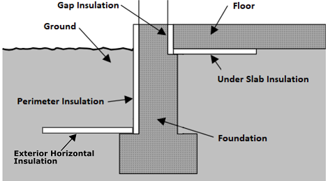
PerimeterInsulation/Layer/NominalRValuedouble
F-ft2-hr/Btu
>= 0
Yes
R-value of vertical insulation (see figure below)
PerimeterInsulation/Layer/InsulationDepthdouble
ft
>= 0
Yes
Depth from top of slab to bottom of vertical insulation
ExteriorHorizontalInsulation/SystemIdentifierid
See [202]
Unique identifier
ExteriorHorizontalInsulation/Layer/NominalRValuedouble
F-ft2-hr/Btu
>= 0
No
0
R-value of exterior horizontal insulation (see figure below) [203]
ExteriorHorizontalInsulation/Layer/InsulationWidthdouble
ft
>= 0
No
0
Width of exterior horizontal insulation from slab edge outward
ExteriorHorizontalInsulation/Layer/InsulationDepthBelowGradedouble
ft
>= 0
No
0
Depth from grade to the top of exterior horizontal insulation
UnderSlabInsulation/SystemIdentifierid
Yes
Unique identifier
UnderSlabInsulation/Layer/NominalRValuedouble
F-ft2-hr/Btu
>= 0
Yes
R-value of horizontal insulation (see figure below)
UnderSlabInsulation/Layer/InsulationWidthdouble
ft
>= 0
See [204]
Width from slab edge inward of horizontal insulation
UnderSlabInsulation/Layer/InsulationSpansEntireSlabboolean
See [205]
Whether horizontal insulation spans entire slab
extension/GapInsulationRValuedouble
F-ft2-hr/Btu
>= 0
No
See [206]
R-value of gap insulation (see figure below)
extension/CarpetFractiondouble
frac
>= 0, <= 1
No
See [207]
Fraction of slab covered by carpet
extension/CarpetRValuedouble
F-ft2-hr/Btu
>= 0
No
See [208]
Carpet R-value
An example of calculating slab exposed perimeter is shown below:
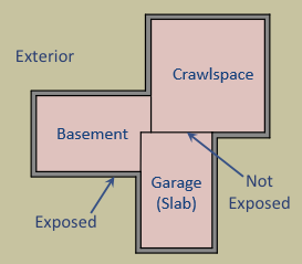
As illustrated above, basement slab edge adjacent to a garage slab or crawlspace is not considered exposed perimeter. It is quite uncommon for a slab to have an exposed perimeter of zero. Heat transfer is only calculated for the length of exposed perimeter; the rest of the perimeter is assumed to have minimal heat transfer.
Slab insulation locations can be visualized in the figure below:
HPXML Windows
Each window or glass door area is entered as a /HPXML/Building/BuildingDetails/Enclosure/Windows/Window.
Element
Type
Units
Constraints
Required
Default
Notes
SystemIdentifierid
Yes
Unique identifier
Areadouble
ft2
> 0
Yes
Total area [209]
AzimuthorOrientationinteger or string
deg or direction
>= 0, <= 359 or See [210]
Yes
Direction (clockwise from North)
UFactorand/orGlassLayersdouble or string
Btu/F-ft2-hr
> 0 or See [211]
Yes
Full-assembly NFRC U-factor or glass layers description [212]
SHGCand/orGlassLayersdouble or string
> 0, < 1
Yes
Full-assembly NFRC solar heat gain coefficient or glass layers description
ExteriorShadingelement
No
<none>
Presence of exterior shading [213]
InteriorShadingelement
No
<present>
Presence of interior shading [214]
InsectScreenelement
No
<none>
Presence of insect screen [215]
StormWindowelement
No
<none>
Presence of storm window [216]
Overhangselement
No
<none>
Presence of overhangs (including roof eaves) [217]
FractionOperabledouble
frac
>= 0, <= 1
No
0.67
Operable fraction [218]
AttachedToWallidref
See [219]
Yes
ID of attached wall
UFactor/SHGC Lookup
If UFactor and SHGC are not provided and GlassLayers is not “glass block”, additional information is entered in Window.
Element
Type
Units
Constraints
Required
Default
Notes
FrameTypeelement
See [220]
Yes
Type of frame
FrameType/*/ThermalBreakboolean
See [221]
No
false
Whether the Aluminum or Metal frame has a thermal break
GlassTypestring
See [222]
No
clear
Type of glass
GasFillstring
See [223]
No
See [224]
Type of gas inside double/triple-pane windows
If UFactor and SHGC are not provided, they are defaulted as follows:
GlassLayers
FrameType
ThermalBreak
GlassType
GasFill
UFactor
SHGC
single-pane
Aluminum, Metal
false
“clear”, “reflective”
–
1.27
0.75
single-pane
Fiberglass, Vinyl, Wood
–
“clear”, “reflective”
–
0.89
0.64
single-pane
Aluminum, Metal
false
“tinted”, “tinted/reflective”
–
1.27
0.64
single-pane
Fiberglass, Vinyl, Wood
–
“tinted”, “tinted/reflective”
–
0.89
0.54
double-pane
Aluminum, Metal
false
“clear”, “reflective”
air
0.81
0.67
double-pane
Aluminum, Metal
true
“clear”, “reflective”
air
0.60
0.67
double-pane
Fiberglass, Vinyl, Wood
–
“clear”, “reflective”
air
0.51
0.56
double-pane
Aluminum, Metal
false
“tinted”, “tinted/reflective”
air
0.81
0.55
double-pane
Aluminum, Metal
true
“tinted”, “tinted/reflective”
air
0.60
0.55
double-pane
Fiberglass, Vinyl, Wood
–
“tinted”, “tinted/reflective”
air
0.51
0.46
double-pane
Fiberglass, Vinyl, Wood
–
“low-e”, “low-e, high-solar-gain”
air
0.42
0.52
double-pane
Aluminum, Metal
true
“low-e”, “low-e, high-solar-gain”
<any but air>
0.47
0.62
double-pane
Fiberglass, Vinyl, Wood
–
“low-e”, “low-e, high-solar-gain”
<any but air>
0.39
0.52
double-pane
Aluminum, Metal
false
“low-e, low-solar-gain”
air
0.67
0.37
double-pane
Aluminum, Metal
true
“low-e, low-solar-gain”
air
0.47
0.37
double-pane
Fiberglass, Vinyl, Wood
–
“low-e, low-solar-gain”
air
0.39
0.31
double-pane
Fiberglass, Vinyl, Wood
–
“low-e, low-solar-gain”
<any but air>
0.36
0.31
triple-pane
Fiberglass, Vinyl, Wood
–
“low-e”, “low-e, high-solar-gain”
<any but air>
0.27
0.31
glass block
–
–
–
–
0.60
0.60
Warning
OpenStudio-HPXML will return an error if the combination of window properties is not in the above table.
HPXML Exterior Shading
If exterior shading is specified, additional information is entered in ExteriorShading.
Either winter/summer shading coefficients can be directly provided, or they can be defaulted from the other inputs.
Element
Type
Units
Constraints
Required
Default
Notes
Typestring
See [225]
No
See [226]
Shading type
SummerFractionCovereddouble
frac
>= 0, <= 1
No
See [227]
Fraction of window area covered by shading in summer
WinterFractionCovereddouble
frac
>= 0, <= 1
No
See [228]
Fraction of window area covered by shading in winter
SummerShadingCoefficientdouble
frac
>= 0, <= 1
No
See [229]
Total summer shading coefficient for modeling (1=transparent, 0=opaque)
WinterShadingCoefficientdouble
frac
>= 0, <= 1
No
See [230]
Total winter shading coefficient for modeling (1=transparent, 0=opaque)
Note
OpenStudio-HPXML directly uses only the SummerShadingCoefficient and WinterShadingCoefficient values (user provided or defaulted) in the energy model.
Summer vs winter shading seasons are determined per HPXML Shading Control.
HPXML Interior Shading
If interior shading is specified, additional information is entered in InteriorShading.
Either winter/summer shading coefficients can be directly provided, or they can be defaulted from the other inputs.
Element
Type
Units
Constraints
Required
Default
Notes
Typestring
See [231]
No
See [232]
Shading type
BlindsSummerClosedOrOpenstring
See [233]
No
half open
Blinds position in summer (only used if shading type is blinds)
BlindsWinterClosedOrOpenstring
See [234]
No
half open
Blinds position in winter (only used if shading type is blinds)
SummerFractionCovereddouble
frac
>= 0, <= 1
No
See [235]
Fraction of window area covered by shading in summer
WinterFractionCovereddouble
frac
>= 0, <= 1
No
See [236]
Fraction of window area covered by shading in winter
SummerShadingCoefficientdouble
frac
>= 0, <= 1
No
See [237]
Total summer shading coefficient for modeling (1=transparent, 0=opaque)
WinterShadingCoefficientdouble
frac
>= 0, <= 1
No
See [238]
Total winter shading coefficient for modeling (1=transparent, 0=opaque)
Note
OpenStudio-HPXML directly uses only the SummerShadingCoefficient and WinterShadingCoefficient values (user provided or defaulted) in the energy model.
Summer vs winter shading seasons are determined per HPXML Shading Control.
HPXML Insect Screen
If an insect screen is specified, additional information is entered in InsectScreen.
Either winter/summer shading coefficients can be directly provided, or they can be defaulted from the other inputs.
Element
Type
Units
Constraints
Required
Default
Notes
Locationstring
See [239]
No
exterior
Whether the screen is on the interior or exterior of the glass
SummerFractionCovereddouble
frac
>= 0, <= 1
No
See [240]
Fraction of window area covered in the summer
WinterFractionCovereddouble
frac
>= 0, <= 1
No
See [241]
Fraction of window area covered in the winter
SummerShadingCoefficientdouble
frac
>= 0, <= 1
No
See [242]
Interior summer shading coefficient for modeling (1=transparent, 0=opaque)
WinterShadingCoefficientdouble
frac
>= 0, <= 1
No
See [243]
Interior winter shading coefficient for modeling (1=transparent, 0=opaque)
Note
OpenStudio-HPXML directly uses only the SummerShadingCoefficient and WinterShadingCoefficient values (user provided or defaulted) in the energy model.
Summer vs winter shading seasons are determined per HPXML Shading Control.
HPXML Storm Window
If a storm window is specified, additional information is entered in StormWindow.
Element
Type
Units
Constraints
Required
Default
Notes
GlassTypestring
See [244]
No
<none>
Type of storm window glass
HPXML Overhangs
If overhangs are specified, additional information is entered in Overhangs.
Natural Ventilation
If operable windows are defined, the availability of natural ventilation is entered in /HPXML/Building/BuildingDetails/BuildingSummary/extension.
Element
Type
Units
Constraints
Required
Default
Notes
NaturalVentilationAvailabilityDaysperWeekinteger
days/week
>= 0, <= 7
No
3 [247]
How often windows can be opened by occupants for natural ventilation
HPXML Skylights
Each skylight is entered as a /HPXML/Building/BuildingDetails/Enclosure/Skylights/Skylight.
Element
Type
Units
Constraints
Required
Default
Notes
SystemIdentifierid
Yes
Unique identifier
Areadouble
ft2
> 0
Yes
Total area [248]
AzimuthorOrientationinteger or string
deg or direction
>= 0, <= 359 or See [249]
Yes
Direction (clockwise from North)
UFactorand/orGlassLayersdouble or string
Btu/F-ft2-hr
> 0 or See [250]
Yes
Full-assembly NFRC U-factor or glass layers description [251]
SHGCand/orGlassLayersdouble or string
> 0, < 1
Yes
Full-assembly NFRC solar heat gain coefficient or glass layers description
ExteriorShadingelement
No
<none>
Presence of exterior shading [252]
InteriorShadingelement
No
<none>
Presence of interior shading [253]
StormWindowelement
No
<none>
Presence of storm window [254]
AttachedToRoofidref
See [255]
Yes
ID of attached roof
AttachedToFlooridref
See [256]
See [257]
ID of attached attic floor
extension/Curbelement
No
<none>
Presence of curb (skylight wall above the roof deck) [258]
extension/Shaftelement
No
<none>
Presence of shaft (skylight wall below the roof deck) [259]
UFactor/SHGC Lookup
If UFactor and SHGC are not provided and GlassLayers is not “glass block”, additional information is entered in Skylight.
Element
Type
Units
Constraints
Required
Default
Notes
FrameTypeelement
See [260]
Yes
Type of frame
FrameType/*/ThermalBreakboolean
See [261]
No
false
Whether the Aluminum or Metal frame has a thermal break
GlassTypestring
See [262]
No
<none>
Type of glass
GasFillstring
See [263]
No
See [264]
Type of gas inside double/triple-pane skylights
If UFactor and SHGC are not provided, they are defaulted as follows:
GlassLayers
FrameType
ThermalBreak
GlassType
GasFill
UFactor
SHGC
single-pane
Aluminum, Metal
false
“clear”, “reflective”
–
1.98
0.75
single-pane
Fiberglass, Vinyl, Wood
–
“clear”, “reflective”
–
1.47
0.64
single-pane
Aluminum, Metal
false
“tinted”, “tinted/reflective”
–
1.98
0.64
single-pane
Fiberglass, Vinyl, Wood
–
“tinted”, “tinted/reflective”
–
1.47
0.54
double-pane
Aluminum, Metal
false
“clear”, “reflective”
air
1.30
0.67
double-pane
Aluminum, Metal
true
“clear”, “reflective”
air
1.10
0.67
double-pane
Fiberglass, Vinyl, Wood
–
“clear”, “reflective”
air
0.84
0.56
double-pane
Aluminum, Metal
false
“tinted”, “tinted/reflective”
air
1.30
0.55
double-pane
Aluminum, Metal
true
“tinted”, “tinted/reflective”
air
1.10
0.55
double-pane
Fiberglass, Vinyl, Wood
–
“tinted”, “tinted/reflective”
air
0.84
0.46
double-pane
Fiberglass, Vinyl, Wood
–
“low-e”, “low-e, high-solar-gain”
air
0.74
0.52
double-pane
Aluminum, Metal
true
“low-e”, “low-e, high-solar-gain”
<any but air>
0.95
0.62
double-pane
Fiberglass, Vinyl, Wood
–
“low-e”, “low-e, high-solar-gain”
<any but air>
0.68
0.52
double-pane
Aluminum, Metal
false
“low-e, low-solar-gain”
air
1.17
0.37
double-pane
Aluminum, Metal
true
“low-e, low-solar-gain”
air
0.98
0.37
double-pane
Fiberglass, Vinyl, Wood
–
“low-e, low-solar-gain”
air
0.71
0.31
double-pane
Fiberglass, Vinyl, Wood
–
“low-e, low-solar-gain”
<any but air>
0.65
0.31
triple-pane
Fiberglass, Vinyl, Wood
–
“low-e”, “low-e, high-solar-gain”
<any but air>
0.47
0.31
glass block
–
–
–
–
0.60
0.60
Warning
OpenStudio-HPXML will return an error if the combination of skylight properties is not in the above table.
HPXML Exterior Shading
If exterior shading is present, additional information is entered in ExteriorShading.
Element
Type
Units
Constraints
Required
Default
Notes
SummerShadingCoefficientdouble
frac
>= 0, <= 1
No
1.0
Exterior summer shading coefficient (1=transparent, 0=opaque)
WinterShadingCoefficientdouble
frac
>= 0, <= 1
No
1.0
Exterior winter shading coefficient (1=transparent, 0=opaque)
Note
Summer vs winter shading seasons are determined per HPXML Shading Control.
HPXML Interior Shading
If interior shading is present, additional information is entered in InteriorShading.
Element
Type
Units
Constraints
Required
Default
Notes
SummerShadingCoefficientdouble
frac
>= 0, <= 1
No
1.0
Interior summer shading coefficient (1=transparent, 0=opaque)
WinterShadingCoefficientdouble
frac
>= 0, <= 1
No
1.0
Interior winter shading coefficient (1=transparent, 0=opaque)
Note
Summer vs winter shading seasons are determined per HPXML Shading Control.
HPXML Storm Window
If a storm window is specified, additional information is entered in StormWindow.
Element
Type
Units
Constraints
Required
Default
Notes
GlassTypestring
See [265]
No
<none>
Type of storm window glass
Skylight Curb
If the skylight has a curb, additional information is entered in Skylight.
Element
Type
Units
Constraints
Required
Default
Notes
extension/Curb/Areadouble
ft2
> 0
Yes
Total area including all sides
extension/Curb/AssemblyEffectiveRValuedouble
F-ft2-hr/Btu
> 0
Yes
Assembly R-value [266]
Skylight Shaft
If the skylight has a shaft, additional information is entered in Skylight.
Element
Type
Units
Constraints
Required
Default
Notes
extension/Shaft/Areadouble
ft2
> 0
Yes
Total area including all sides
extension/Shaft/AssemblyEffectiveRValuedouble
F-ft2-hr/Btu
> 0
Yes
Assembly R-value [267]
HPXML Doors
Each door with opaque area is entered as a /HPXML/Building/BuildingDetails/Enclosure/Doors/Door.
Element
Type
Units
Constraints
Required
Default
Notes
SystemIdentifierid
Yes
Unique identifier
AttachedToWallidref
See [268]
Yes
ID of attached wall
Areadouble
ft2
> 0
Yes
Total opaque area [269]
AzimuthorOrientationinteger or string
deg
>= 0, <= 359 or See [270]
No
See [271]
Direction (clockwise from North)
RValuedouble
F-ft2-hr/Btu
> 0
Yes
R-value [272]
HPXML Partition Wall Mass
Partition wall mass in the conditioned space is entered as /HPXML/Building/BuildingDetails/Enclosure/extension/PartitionWallMass.
Element
Type
Units
Constraints
Required
Default
Notes
AreaFractiondouble
frac
>= 0
No
1.0
Fraction of both sides of wall area to conditioned floor area
InteriorFinish/Typestring
See [273]
No
gypsum board
Interior finish material
InteriorFinish/Thicknessdouble
in
>= 0
No
0.5
Interior finish thickness
HPXML Furniture Mass
Furniture mass in the conditioned space is entered as /HPXML/Building/BuildingDetails/Enclosure/extension/FurnitureMass.
Element
Type
Units
Constraints
Required
Default
Notes
AreaFractiondouble
frac
>= 0
No
0.4
Fraction of conditioned floor area covered by furniture
Typestring
See [274]
No
light-weight
Type of furniture
Note
Light-weight furniture is modeled with a weight of 8 lb/ft2 of floor area and a density of 40 lb/ft3 while heavy-weight furniture is modeled with a weight of 16 lb/ft2 of floor area and a density of 80 lb/ft3.
HPXML Systems
The dwelling unit’s systems are entered in /HPXML/Building/BuildingDetails/Systems.
HPXML Heating Systems
The following heating system types can be modeled:
Electric Resistance
Each electric resistance heating system is entered as a /HPXML/Building/BuildingDetails/Systems/HVAC/HVACPlant/HeatingSystem.
Element
Type
Units
Constraints
Required
Default
Notes
SystemIdentifierid
Yes
Unique identifier
AttachedToZoneidref
See [275]
See [276]
ID of attached zone
HeatingSystemType/ElectricResistanceelement
Yes
Type of heating system
HeatingSystemType/ElectricResistance/ElectricDistributionstring
See [277]
No
baseboard
Type of electric resistance distribution
HeatingSystemFuelstring
electricity
Yes
Fuel type
HeatingCapacitydouble
Btu/hr
>= 0
No
autosized [278]
Heating output capacity
AnnualHeatingEfficiency[Units="Percent"]/Valuedouble
frac
> 0, <= 1
Yes
Heating efficiency
FractionHeatLoadServeddouble
frac
>= 0, <= 1 [279]
See [280]
Fraction of heating load served
extension/HeatingAutosizingFactordouble
frac
> 0
No
1.0
Heating autosizing capacity multiplier
extension/HeatingAutosizingLimitdouble
Btu/hr
> 0
No
Heating autosizing capacity limit
Furnace
Each central furnace is entered as a /HPXML/Building/BuildingDetails/Systems/HVAC/HVACPlant/HeatingSystem.
Element
Type
Units
Constraints
Required
Default
Notes
SystemIdentifierid
Yes
Unique identifier
AttachedToZoneidref
See [281]
See [282]
ID of attached zone
UnitLocationstring
See [283]
No
See [284]
Location of air handler
DistributionSystemidref
See [285]
Yes
ID of attached distribution system
HeatingSystemType/Furnaceelement
Yes
Type of heating system
HeatingSystemType/Furnace/PilotLightboolean
No
false
Presence of standing pilot light (older systems)
HeatingSystemType/Furnace/extension/PilotLightBtuhdouble
Btu/hr
>= 0
No
500
Pilot light burn rate
HeatingSystemFuelstring
See [286]
Yes
Fuel type
HeatingCapacitydouble
Btu/hr
>= 0
No
autosized [287]
Heating output capacity
AnnualHeatingEfficiency[Units="AFUE"]/Valuedouble
frac
> 0, <= 1
Yes
Rated heating efficiency
FractionHeatLoadServeddouble
frac
>= 0, <= 1 [288]
See [289]
Fraction of heating load served
extension/FanMotorTypestring
See [290]
No
See [291]
Blower fan model type
extension/FanPowerWattsPerCFMdouble
W/cfm
>= 0 [292]
No
See [293]
Blower fan efficiency at maximum fan speed
extension/HeatingDesignAirflowCFMdouble
cfm
>= 0
No
240 cfm/ton
Blower fan heating design airflow rate
extension/AirflowDefectRatiodouble
frac
>= -0.9, <= 9
No
0.0
Deviation between design/installed airflow rates [294]
extension/HeatingAutosizingFactordouble
frac
> 0
No
1.0
Heating autosizing capacity multiplier
extension/HeatingAutosizingLimitdouble
Btu/hr
> 0
No
Heating autosizing capacity limit
Wall Furnace
Each wall furnace is entered as a /HPXML/Building/BuildingDetails/Systems/HVAC/HVACPlant/HeatingSystem.
Element
Type
Units
Constraints
Required
Default
Notes
SystemIdentifierid
Yes
Unique identifier
AttachedToZoneidref
See [295]
See [296]
ID of attached zone
HeatingSystemType/WallFurnaceelement
Yes
Type of heating system
HeatingSystemType/WallFurnace/PilotLightboolean
No
false
Presence of standing pilot light (older systems)
HeatingSystemType/WallFurnace/extension/PilotLightBtuhdouble
Btu/hr
>= 0
No
500
Pilot light burn rate
HeatingSystemFuelstring
See [297]
Yes
Fuel type
HeatingCapacitydouble
Btu/hr
>= 0
No
autosized [298]
Heating output capacity
AnnualHeatingEfficiency[Units="AFUE"]/Valuedouble
frac
> 0, <= 1
Yes
Rated heating efficiency
FractionHeatLoadServeddouble
frac
>= 0, <= 1 [299]
See [300]
Fraction of heating load served
extension/FanPowerWattsdouble
W
>= 0
No
0
Fan power
extension/HeatingAutosizingFactordouble
frac
> 0
No
1.0
Heating autosizing capacity multiplier
extension/HeatingAutosizingLimitdouble
Btu/hr
> 0
No
Heating autosizing capacity limit
Floor Furnace
Each floor furnace is entered as a /HPXML/Building/BuildingDetails/Systems/HVAC/HVACPlant/HeatingSystem.
Element
Type
Units
Constraints
Required
Default
Notes
SystemIdentifierid
Yes
Unique identifier
AttachedToZoneidref
See [301]
See [302]
ID of attached zone
HeatingSystemType/FloorFurnaceelement
Yes
Type of heating system
HeatingSystemType/FloorFurnace/PilotLightboolean
No
false
Presence of standing pilot light (older systems)
HeatingSystemType/FloorFurnace/extension/PilotLightBtuhdouble
Btu/hr
>= 0
No
500
Pilot light burn rate
HeatingSystemFuelstring
See [303]
Yes
Fuel type
HeatingCapacitydouble
Btu/hr
>= 0
No
autosized [304]
Heating output capacity
AnnualHeatingEfficiency[Units="AFUE"]/Valuedouble
frac
> 0, <= 1
Yes
Rated heating efficiency
FractionHeatLoadServeddouble
frac
>= 0, <= 1 [305]
See [306]
Fraction of heating load served
extension/FanPowerWattsdouble
W
>= 0
No
0
Fan power
extension/HeatingAutosizingFactordouble
frac
> 0
No
1.0
Heating autosizing capacity multiplier
extension/HeatingAutosizingLimitdouble
Btu/hr
> 0
No
Heating autosizing capacity limit
Boiler (In-Unit)
Each in-unit boiler is entered as a /HPXML/Building/BuildingDetails/Systems/HVAC/HVACPlant/HeatingSystem.
Element
Type
Units
Constraints
Required
Default
Notes
SystemIdentifierid
Yes
Unique identifier
AttachedToZoneidref
See [307]
See [308]
ID of attached zone
UnitLocationstring
See [309]
No
See [310]
Location of boiler
DistributionSystemidref
See [311]
Yes
ID of attached distribution system
HeatingSystemType/Boilerelement
Yes
Type of heating system
HeatingSystemType/Boiler/PilotLightboolean
No
false
Presence of standing pilot light (older systems)
HeatingSystemType/Boiler/extension/PilotLightBtuhdouble
Btu/hr
>= 0
No
500
Pilot light burn rate
HeatingSystemFuelstring
See [312]
Yes
Fuel type
HeatingCapacitydouble
Btu/hr
>= 0
No
autosized [313]
Heating output capacity
AnnualHeatingEfficiency[Units="AFUE"]/Valuedouble
frac
> 0, <= 1
Yes
Rated heating efficiency
FractionHeatLoadServeddouble
frac
>= 0, <= 1 [314]
See [315]
Fraction of heating load served
ElectricAuxiliaryEnergydouble
kWh/yr
>= 0
No
See [316]
Electric auxiliary energy
extension/HeatingAutosizingFactordouble
frac
> 0
No
1.0
Heating autosizing capacity multiplier
extension/HeatingAutosizingLimitdouble
Btu/hr
> 0
No
Heating autosizing capacity limit
Stove
Each stove is entered as a /HPXML/Building/BuildingDetails/Systems/HVAC/HVACPlant/HeatingSystem.
Element
Type
Units
Constraints
Required
Default
Notes
SystemIdentifierid
Yes
Unique identifier
AttachedToZoneidref
See [326]
See [327]
ID of attached zone
HeatingSystemType/Stoveelement
Yes
Type of heating system
HeatingSystemType/Stove/PilotLightboolean
No
false
Presence of standing pilot light (older systems)
HeatingSystemType/Stove/extension/PilotLightBtuhdouble
Btu/hr
>= 0
No
500
Pilot light burn rate
HeatingSystemFuelstring
See [328]
Yes
Fuel type
HeatingCapacitydouble
Btu/hr
>= 0
No
autosized [329]
Heating output capacity
AnnualHeatingEfficiency[Units="Percent"]/Valuedouble
frac
> 0, <= 1
Yes
Heating efficiency
FractionHeatLoadServeddouble
frac
>= 0, <= 1 [330]
See [331]
Fraction of heating load served
extension/FanPowerWattsdouble
W
>= 0
No
40
Fan power
extension/HeatingAutosizingFactordouble
frac
> 0
No
1.0
Heating autosizing capacity multiplier
extension/HeatingAutosizingLimitdouble
Btu/hr
> 0
No
Heating autosizing capacity limit
Space Heater
Each space heater is entered as a /HPXML/Building/BuildingDetails/Systems/HVAC/HVACPlant/HeatingSystem.
Element
Type
Units
Constraints
Required
Default
Notes
SystemIdentifierid
Yes
Unique identifier
AttachedToZoneidref
See [332]
See [333]
ID of attached zone
HeatingSystemType/SpaceHeaterelement
Yes
Type of heating system
HeatingSystemFuelstring
See [334]
Yes
Fuel type
HeatingCapacitydouble
Btu/hr
>= 0
No
autosized [335]
Heating output capacity
AnnualHeatingEfficiency[Units="Percent"]/Valuedouble
frac
> 0, <= 1
Yes
Heating efficiency
FractionHeatLoadServeddouble
frac
>= 0, <= 1 [336]
See [337]
Fraction of heating load served
extension/FanPowerWattsdouble
W
>= 0
No
0
Fan power
extension/HeatingAutosizingFactordouble
frac
> 0
No
1.0
Heating autosizing capacity multiplier
extension/HeatingAutosizingLimitdouble
Btu/hr
> 0
No
Heating autosizing capacity limit
Fireplace
Each fireplace is entered as a /HPXML/Building/BuildingDetails/Systems/HVAC/HVACPlant/HeatingSystem.
Instead of modeling fireplaces as serving a fraction of the heating load, fireplaces can be assigned a therm/year usage using HPXML Fuel Loads.
Element
Type
Units
Constraints
Required
Default
Notes
SystemIdentifierid
Yes
Unique identifier
AttachedToZoneidref
See [338]
See [339]
ID of attached zone
HeatingSystemType/Fireplaceelement
Yes
Type of heating system
HeatingSystemType/Fireplace/PilotLightboolean
No
false
Presence of standing pilot light (older systems)
HeatingSystemType/Fireplace/extension/PilotLightBtuhdouble
Btu/hr
>= 0
No
500
Pilot light burn rate
HeatingSystemFuelstring
See [340]
Yes
Fuel type
HeatingCapacitydouble
Btu/hr
>= 0
No
autosized [341]
Heating output capacity
AnnualHeatingEfficiency[Units="Percent"]/Valuedouble
frac
> 0, <= 1
Yes
Heating efficiency
FractionHeatLoadServeddouble
frac
>= 0, <= 1 [342]
See [343]
Fraction of heating load served
extension/FanPowerWattsdouble
W
>= 0
No
0
Fan power
extension/HeatingAutosizingFactordouble
frac
> 0
No
1.0
Heating autosizing capacity multiplier
extension/HeatingAutosizingLimitdouble
Btu/hr
> 0
No
Heating autosizing capacity limit
HPXML Cooling Systems
The following cooling system types can be modeled:
Central Air Conditioner
Each central air conditioner is entered as a /HPXML/Building/BuildingDetails/Systems/HVAC/HVACPlant/CoolingSystem.
Element
Type
Units
Constraints
Required
Default
Notes
SystemIdentifierid
Yes
Unique identifier
AttachedToZoneidref
See [344]
See [345]
ID of attached zone
UnitLocationstring
See [346]
No
See [347]
Location of air handler
DistributionSystemidref
See [348]
Yes
ID of attached distribution system
CoolingSystemTypestring
central air conditioner
Yes
Type of cooling system
CoolingSystemFuelstring
electricity
Yes
Fuel type
CoolingCapacitydouble
Btu/hr
>= 0
No
autosized [349]
Cooling output capacity
CompressorTypestring
See [350]
Yes
Type of compressor
FractionCoolLoadServeddouble
frac
>= 0, <= 1 [351]
Yes
Fraction of cooling load served
AnnualCoolingEfficiency[Units="SEER2" or Units="SEER"]/Valuedouble
Btu/Wh
> 0
Yes
Rated cooling efficiency [352]
AnnualCoolingEfficiency[Units="EER2" or Units="EER"]/Valuedouble
Btu/Wh
> 0 [353]
No
See [354]
Rated cooling efficiency [355]
CoolingDetailedPerformanceDataelement
No
<none>
Cooling detailed performance data [356]
extension/FanMotorTypestring
See [357]
No
See [358]
Blower fan model type
extension/FanPowerWattsPerCFMdouble
W/cfm
>= 0 [359]
No
See [360]
Blower fan efficiency at maximum fan speed
extension/CoolingDesignAirflowCFMdouble
cfm
>= 0
No
360 cfm/ton
Blower fan cooling design airflow rate
extension/AirflowDefectRatiodouble
frac
>= -0.9, <= 9
No
0.0
Deviation between design/installed airflow rates [361]
extension/ChargeDefectRatiodouble
frac
>= -0.9, <= 9
No
0.0
Deviation between design/installed refrigerant charges [362]
extension/CrankcaseHeaterPowerWattsdouble
W
>= 0
No
See [363]
Crankcase heater power
extension/CoolingAutosizingFactordouble
frac
> 0
No
1.0
Cooling autosizing capacity multiplier
extension/CoolingAutosizingLimitdouble
Btu/hr
> 0
No
Cooling autosizing capacity limit
extension/EquipmentTypestring
See [364]
No
split system
Equipment type only used for SEER/SEER2 and EER/EER2 conversions
Room Air Conditioner
Each room air conditioner is entered as a /HPXML/Building/BuildingDetails/Systems/HVAC/HVACPlant/CoolingSystem.
Element
Type
Units
Constraints
Required
Default
Notes
SystemIdentifierid
Yes
Unique identifier
AttachedToZoneidref
See [365]
See [366]
ID of attached zone
DistributionSystemidref
See [367]
No
ID of attached distribution system
CoolingSystemTypestring
room air conditioner
Yes
Type of cooling system
CoolingSystemFuelstring
electricity
Yes
Fuel type
CoolingCapacitydouble
Btu/hr
>= 0
No
autosized [368]
Cooling output capacity
FractionCoolLoadServeddouble
frac
>= 0, <= 1 [369]
Yes
Fraction of cooling load served
AnnualCoolingEfficiency[Units="CEER" or Units="EER"]/Valuedouble
Btu/Wh
> 0
Yes
Rated cooling efficiency
IntegratedHeatingSystemFuelstring
See [370]
No
<none>
Fuel type of integrated heater
extension/CrankcaseHeaterPowerWattsdouble
W
>= 0
No
0.0
Crankcase heater power
extension/CoolingAutosizingFactordouble
frac
> 0
No
1.0
Cooling autosizing capacity multiplier
extension/CoolingAutosizingLimitdouble
Btu/hr
> 0
No
Cooling autosizing capacity limit
If the room air conditioner has integrated heating, additional information is entered in CoolingSystem.
Note that a room air conditioner with reverse cycle heating should be entered as a heat pump; see Room Air Conditioner w/ Reverse Cycle.
Element
Type
Units
Constraints
Required
Default
Notes
IntegratedHeatingSystemCapacitydouble
Btu/hr
>= 0
No
autosized [371]
Heating output capacity of integrated heater
IntegratedHeatingSystemAnnualEfficiency[Units="Percent"]/Valuedouble
frac
> 0, <= 1
Yes
Efficiency of integrated heater
IntegratedHeatingSystemFractionHeatLoadServeddouble
frac
>= 0, <= 1 [372]
Yes
Fraction of heating load served
Packaged Terminal Air Conditioner
Each packaged terminal air conditioner (PTAC) is entered as a /HPXML/Building/BuildingDetails/Systems/HVAC/HVACPlant/CoolingSystem.
Element
Type
Units
Constraints
Required
Default
Notes
SystemIdentifierid
Yes
Unique identifier
AttachedToZoneidref
See [373]
See [374]
ID of attached zone
DistributionSystemidref
See [375]
No
ID of attached distribution system
CoolingSystemTypestring
packaged terminal air conditioner
Yes
Type of cooling system
CoolingSystemFuelstring
electricity
Yes
Fuel type
CoolingCapacitydouble
Btu/hr
>= 0
No
autosized [376]
Cooling output capacity
FractionCoolLoadServeddouble
frac
>= 0, <= 1 [377]
Yes
Fraction of cooling load served
AnnualCoolingEfficiency[Units="CEER" or Units="EER"]/Valuedouble
Btu/Wh
> 0
Yes
Rated cooling efficiency
IntegratedHeatingSystemFuelstring
See [378]
No
<none>
Fuel type of integrated heater
extension/CrankcaseHeaterPowerWattsdouble
W
>= 0
No
0.0
Crankcase heater power
extension/CoolingAutosizingFactordouble
frac
> 0
No
1.0
Cooling autosizing capacity multiplier
extension/CoolingAutosizingLimitdouble
Btu/hr
> 0
No
Cooling autosizing capacity limit
If the PTAC has integrated heating, additional information is entered in CoolingSystem.
Note that a packaged terminal heat pump should be entered as a heat pump; see Packaged Terminal Heat Pump.
Element
Type
Units
Constraints
Required
Default
Notes
IntegratedHeatingSystemCapacitydouble
Btu/hr
>= 0
No
autosized [379]
Heating output capacity of integrated heater
IntegratedHeatingSystemAnnualEfficiency[Units="Percent"]/Valuedouble
frac
> 0, <= 1
Yes
Efficiency of integrated heater
IntegratedHeatingSystemFractionHeatLoadServeddouble
frac
>= 0, <= 1 [380]
Yes
Fraction of heating load served
Evaporative Cooler
Each evaporative cooler is entered as a /HPXML/Building/BuildingDetails/Systems/HVAC/HVACPlant/CoolingSystem.
Element
Type
Units
Constraints
Required
Default
Notes
SystemIdentifierid
Yes
Unique identifier
AttachedToZoneidref
See [381]
See [382]
ID of attached zone
DistributionSystemidref
See [383]
No
ID of attached distribution system
CoolingSystemTypestring
evaporative cooler
Yes
Type of cooling system
CoolingSystemFuelstring
electricity
Yes
Fuel type
CoolingCapacitydouble
Btu/hr
>= 0
No
autosized [384]
Cooling output capacity
FractionCoolLoadServeddouble
frac
>= 0, <= 1 [385]
Yes
Fraction of cooling load served
extension/CoolingAutosizingFactordouble
frac
> 0
No
1.0
Cooling autosizing capacity multiplier
extension/CoolingAutosizingLimitdouble
Btu/hr
> 0
No
Cooling autosizing capacity limit
Mini-Split Air Conditioner
Each mini-split air conditioner is entered as a /HPXML/Building/BuildingDetails/Systems/HVAC/HVACPlant/CoolingSystem.
Element
Type
Units
Constraints
Required
Default
Notes
SystemIdentifierid
Yes
Unique identifier
AttachedToZoneidref
See [386]
See [387]
ID of attached zone
UnitLocationstring
See [388]
No
See [389]
Location of air handler
DistributionSystemidref
See [390]
No
ID of attached distribution system
CoolingSystemTypestring
mini-split
Yes
Type of cooling system
CoolingSystemFuelstring
electricity
Yes
Fuel type
CoolingCapacitydouble
Btu/hr
>= 0
No
autosized [391]
Cooling output capacity
CompressorTypestring
variable speed
Yes
Type of compressor
FractionCoolLoadServeddouble
frac
>= 0, <= 1 [392]
Yes
Fraction of cooling load served
AnnualCoolingEfficiency[Units="SEER2" or Units="SEER"]/Valuedouble
Btu/Wh
> 0
Yes
Rated cooling efficiency [393]
AnnualCoolingEfficiency[Units="EER2" or Units="EER"]/Valuedouble
Btu/Wh
> 0 [394]
No
See [395]
Rated cooling efficiency [396]
CoolingDetailedPerformanceDataelement
No
<none>
Cooling detailed performance data [397]
extension/FanMotorTypestring
See [398]
No
BPM
Blower fan model type
extension/FanPowerWattsPerCFMdouble
W/cfm
>= 0 [399]
No
See [400]
Blower fan efficiency at maximum fan speed
extension/CoolingDesignAirflowCFMdouble
cfm
>= 0
No
360 cfm/ton
Blower fan cooling design airflow rate
extension/AirflowDefectRatiodouble
frac
>= -0.9, <= 9
No
0.0
Deviation between design/installed airflow rates [401]
extension/ChargeDefectRatiodouble
frac
>= -0.9, <= 9
No
0.0
Deviation between design/installed refrigerant charges [402]
extension/CrankcaseHeaterPowerWattsdouble
W
>= 0
No
See [403]
Crankcase heater power
extension/CoolingAutosizingFactordouble
frac
> 0
No
1.0
Cooling autosizing capacity multiplier
extension/CoolingAutosizingLimitdouble
Btu/hr
> 0
No
Cooling autosizing capacity limit
HPXML Heat Pumps
The following heat pump types can be modeled:
Air-to-Air Heat Pump
Each air-to-air heat pump is entered as a /HPXML/Building/BuildingDetails/Systems/HVAC/HVACPlant/HeatPump.
Element
Type
Units
Constraints
Required
Default
Notes
SystemIdentifierid
Yes
Unique identifier
AttachedToZoneidref
See [413]
See [414]
ID of attached zone
UnitLocationstring
See [415]
No
See [416]
Location of air handler
DistributionSystemidref
See [417]
Yes
ID of attached distribution system
HeatPumpTypestring
air-to-air
Yes
Type of heat pump
HeatPumpFuelstring
electricity
Yes
Fuel type
HeatingCapacitydouble
Btu/hr
>= 0
No
autosized [418]
Heating output capacity at 47F
HeatingCapacity17Fdouble
Btu/hr
>= 0, <= HeatingCapacity
No
Heating output capacity at 17F
CoolingCapacitydouble
Btu/hr
>= 0
No
autosized [419]
Cooling output capacity
CompressorTypestring
See [420]
Yes
Type of compressor
CompressorLockoutTemperaturedouble
F
No
See [421]
Minimum outdoor temperature for compressor operation
BackupTypestring
See [422]
No
<none>
Type of backup heating
FractionHeatLoadServeddouble
frac
>= 0, <= 1 [423]
Yes
Fraction of heating load served
FractionCoolLoadServeddouble
frac
>= 0, <= 1 [424]
Yes
Fraction of cooling load served
AnnualCoolingEfficiency[Units="SEER2" or Units="SEER"]/Valuedouble
Btu/Wh
> 0
Yes
Rated cooling efficiency [425]
AnnualCoolingEfficiency[Units="EER2" or Units="EER"]/Valuedouble
Btu/Wh
> 0 [426]
No
See [427]
Rated cooling efficiency [428]
AnnualHeatingEfficiency[Units="HSPF2" or Units="HSPF"]/Valuedouble
Btu/Wh
> 0
Yes
Rated heating efficiency [429]
CoolingDetailedPerformanceDataelement
No
<none>
Cooling detailed performance data [430]
HeatingDetailedPerformanceDataelement
No
<none>
Heating detailed performance data [431]
extension/HeatingCapacityFraction17Fdouble
frac
>= 0, < 1
No
See [432]
Heating output capacity at 17F divided by heating output capacity at 47F [433]
extension/FanMotorTypestring
See [434]
No
See [435]
Blower fan model type
extension/FanPowerWattsPerCFMdouble
W/cfm
>= 0
No
See [436]
Blower fan efficiency at maximum fan speed
extension/HeatingDesignAirflowCFMdouble
cfm
>= 0
No
See [437]
Blower fan heating design airflow rate
extension/CoolingDesignAirflowCFMdouble
cfm
>= 0
No
See [438]
Blower fan cooling design airflow rate
extension/AirflowDefectRatiodouble
frac
>= -0.9, <= 9
No
0.0
Deviation between design/installed airflow rates [439]
extension/ChargeDefectRatiodouble
frac
>= -0.9, <= 9
No
0.0
Deviation between design/installed refrigerant charges [440]
extension/CrankcaseHeaterPowerWattsdouble
W
>= 0
No
See [441]
Crankcase heater power
extension/PanHeaterPowerWattsdouble
W
>= 0
No
150.0
Pan heater power
extension/PanHeaterControlTypestring
See [442]
No
continuous
Pan heater control type [443]
extension/BackupHeatingActiveDuringDefrostboolean
No
See [444]
Whether integrated backup heat is used during defrost [445]
extension/CoolingAutosizingFactordouble
frac
> 0
No
1.0
Cooling autosizing capacity multiplier
extension/HeatingAutosizingFactordouble
frac
> 0
No
1.0
Heating autosizing capacity multiplier
extension/CoolingAutosizingLimitdouble
Btu/hr
> 0
No
Cooling autosizing capacity limit
extension/HeatingAutosizingLimitdouble
Btu/hr
> 0
No
Heating autosizing capacity limit
extension/EquipmentTypestring
See [446]
No
split system
Equipment type only used for SEER/SEER2, EER/EER2, and HSPF/HSPF2 conversions
Mini-Split Heat Pump
Each mini-split heat pump is entered as a /HPXML/Building/BuildingDetails/Systems/HVAC/HVACPlant/HeatPump.
Each HeatPump should represent a single outdoor unit, whether connected to one indoor head or multiple indoor heads.
Element
Type
Units
Constraints
Required
Default
Notes
SystemIdentifierid
Yes
Unique identifier
AttachedToZoneidref
See [447]
See [448]
ID of attached zone
UnitLocationstring
See [449]
No
See [450]
Location of air handler
DistributionSystemidref
See [451]
No
ID of attached distribution system, if present
HeatPumpTypestring
mini-split
Yes
Type of heat pump
HeatPumpFuelstring
electricity
Yes
Fuel type
HeatingCapacitydouble
Btu/hr
>= 0
No
autosized [452]
Heating output capacity at 47F
HeatingCapacity17Fdouble
Btu/hr
>= 0, <= HeatingCapacity
No
Heating output capacity at 17F
CoolingCapacitydouble
Btu/hr
>= 0
No
autosized [453]
Cooling output capacity
CompressorTypestring
variable speed
Yes
Type of compressor
CompressorLockoutTemperaturedouble
F
No
See [454]
Minimum outdoor temperature for compressor operation
BackupTypestring
See [455]
No
<none>
Type of backup heating
FractionHeatLoadServeddouble
frac
>= 0, <= 1 [456]
Yes
Fraction of heating load served
FractionCoolLoadServeddouble
frac
>= 0, <= 1 [457]
Yes
Fraction of cooling load served
AnnualCoolingEfficiency[Units="SEER2" or Units="SEER"]/Valuedouble
Btu/Wh
> 0
Yes
Rated cooling efficiency [458]
AnnualCoolingEfficiency[Units="EER2" or Units="EER"]/Valuedouble
Btu/Wh
> 0 [459]
No
See [460]
Rated cooling efficiency [461]
AnnualHeatingEfficiency[Units="HSPF2" or Units="HSPF"]/Valuedouble
Btu/Wh
> 0
Yes
Rated heating efficiency [462]
CoolingDetailedPerformanceDataelement
No
<none>
Cooling detailed performance data [463]
HeatingDetailedPerformanceDataelement
No
<none>
Heating detailed performance data [464]
extension/HeatingCapacityFraction17Fdouble
frac
>= 0, < 1
No
See [465]
Heating output capacity at 17F divided by heating output capacity at 47F [466]
extension/FanMotorTypestring
See [467]
No
BPM
Blower fan model type
extension/FanPowerWattsPerCFMdouble
W/cfm
>= 0
No
See [468]
Blower fan efficiency at maximum fan speed
extension/HeatingDesignAirflowCFMdouble
cfm
>= 0
No
See [469]
Blower fan heating design airflow rate
extension/CoolingDesignAirflowCFMdouble
cfm
>= 0
No
See [470]
Blower fan cooling design airflow rate
extension/AirflowDefectRatiodouble
frac
>= -0.9, <= 9
No
0.0
Deviation between design/installed airflow rates [471]
extension/ChargeDefectRatiodouble
frac
>= -0.9, <= 9
No
0.0
Deviation between design/installed refrigerant charges [472]
extension/CrankcaseHeaterPowerWattsdouble
W
>= 0
No
See [473]
Crankcase heater power
extension/PanHeaterPowerWattsdouble
W
>= 0
No
150.0
Pan heater power
extension/PanHeaterControlTypestring
See [474]
No
continuous
Pan heater control type [475]
extension/BackupHeatingActiveDuringDefrostboolean
No
See [476]
Whether integrated backup heat is used during defrost [477]
extension/CoolingAutosizingFactordouble
frac
> 0
No
1.0
Cooling autosizing capacity multiplier
extension/HeatingAutosizingFactordouble
frac
> 0
No
1.0
Heating autosizing capacity multiplier
extension/CoolingAutosizingLimitdouble
Btu/hr
> 0
No
Cooling autosizing capacity limit
extension/HeatingAutosizingLimitdouble
Btu/hr
> 0
No
Heating autosizing capacity limit
Packaged Terminal Heat Pump
Each packaged terminal heat pump is entered as a /HPXML/Building/BuildingDetails/Systems/HVAC/HVACPlant/HeatPump.
Element
Type
Units
Constraints
Required
Default
Notes
SystemIdentifierid
Yes
Unique identifier
AttachedToZoneidref
See [478]
See [479]
ID of attached zone
DistributionSystemidref
See [480]
No
ID of attached distribution system
HeatPumpTypestring
packaged terminal heat pump
Yes
Type of heat pump
HeatPumpFuelstring
electricity
Yes
Fuel type
HeatingCapacitydouble
Btu/hr
>= 0
No
autosized [481]
Heating output capacity at 47F
HeatingCapacity17Fdouble
Btu/hr
>= 0, <= HeatingCapacity
No
Heating output capacity at 17F
CoolingCapacitydouble
Btu/hr
>= 0
No
autosized [482]
Cooling output capacity
CompressorLockoutTemperaturedouble
F
No
See [483]
Minimum outdoor temperature for compressor operation
BackupTypestring
See [484]
No
<none>
Type of backup heating
FractionHeatLoadServeddouble
frac
>= 0, <= 1 [485]
Yes
Fraction of heating load served
FractionCoolLoadServeddouble
frac
>= 0, <= 1 [486]
Yes
Fraction of cooling load served
AnnualCoolingEfficiency[Units="CEER" or Units="EER"]/Valuedouble
Btu/Wh
> 0
Yes
Rated cooling efficiency
AnnualHeatingEfficiency[Units="COP"]/Valuedouble
W/W
> 0
Yes
Rated heating efficiency
extension/HeatingCapacityFraction17Fdouble
frac
>= 0, < 1
No
See [487]
Heating output capacity at 17F divided by heating output capacity at 47F [488]
extension/CrankcaseHeaterPowerWattsdouble
W
>= 0
No
0.0
Crankcase heater power
extension/BackupHeatingActiveDuringDefrostboolean
No
false
Whether integrated backup heat is used during defrost [489]
extension/CoolingAutosizingFactordouble
frac
> 0
No
1.0
Cooling autosizing capacity multiplier
extension/HeatingAutosizingFactordouble
frac
> 0
No
1.0
Heating autosizing capacity multiplier
extension/CoolingAutosizingLimitdouble
Btu/hr
> 0
No
Cooling autosizing capacity limit
extension/HeatingAutosizingLimitdouble
Btu/hr
> 0
No
Heating autosizing capacity limit
Room Air Conditioner w/ Reverse Cycle
Each room air conditioner with reverse cycle is entered as a /HPXML/Building/BuildingDetails/Systems/HVAC/HVACPlant/HeatPump.
Element
Type
Units
Constraints
Required
Default
Notes
SystemIdentifierid
Yes
Unique identifier
AttachedToZoneidref
See [490]
See [491]
ID of attached zone
DistributionSystemidref
See [492]
No
ID of attached distribution system
HeatPumpTypestring
room air conditioner with reverse cycle
Yes
Type of heat pump
HeatPumpFuelstring
electricity
Yes
Fuel type
HeatingCapacitydouble
Btu/hr
>= 0
No
autosized [493]
Heating output capacity at 47F
HeatingCapacity17Fdouble
Btu/hr
>= 0, <= HeatingCapacity
No
Heating output capacity at 17F
CoolingCapacitydouble
Btu/hr
>= 0
No
autosized [494]
Cooling output capacity
CompressorLockoutTemperaturedouble
F
No
See [495]
Minimum outdoor temperature for compressor operation
BackupTypestring
See [496]
No
<none>
Type of backup heating
FractionHeatLoadServeddouble
frac
>= 0, <= 1 [497]
Yes
Fraction of heating load served
FractionCoolLoadServeddouble
frac
>= 0, <= 1 [498]
Yes
Fraction of cooling load served
AnnualCoolingEfficiency[Units="CEER" or Units="EER"]/Valuedouble
Btu/Wh
> 0
Yes
Rated cooling efficiency
AnnualHeatingEfficiency[Units="COP"]/Valuedouble
W/W
> 0
Yes
Rated heating efficiency
extension/HeatingCapacityFraction17Fdouble
frac
>= 0, < 1
No
See [499]
Heating output capacity at 17F divided by heating output capacity 1t 47F [500]
extension/CrankcaseHeaterPowerWattsdouble
W
>= 0
No
0.0
Crankcase heater power
extension/BackupHeatingActiveDuringDefrostboolean
No
false
Whether integrated backup heat is used during defrost [501]
extension/CoolingAutosizingFactordouble
frac
> 0
No
1.0
Cooling autosizing capacity multiplier
extension/HeatingAutosizingFactordouble
frac
> 0
No
1.0
Heating autosizing capacity multiplier
extension/CoolingAutosizingLimitdouble
Btu/hr
> 0
No
Cooling autosizing capacity limit
extension/HeatingAutosizingLimitdouble
Btu/hr
> 0
No
Heating autosizing capacity limit
Ground-to-Air Heat Pump
Each ground-to-air heat pump is entered as a /HPXML/Building/BuildingDetails/Systems/HVAC/HVACPlant/HeatPump.
Element
Type
Units
Constraints
Required
Default
Notes
SystemIdentifierid
Yes
Unique identifier
AttachedToZoneidref
See [502]
See [503]
ID of attached zone
UnitLocationstring
See [504]
No
See [505]
Location of air handler
DistributionSystemidref
See [506]
Yes
ID of attached distribution system
IsSharedSystemboolean
No
false
Whether it has a shared hydronic circulation loop [507]
HeatPumpTypestring
ground-to-air
Yes
Type of heat pump
HeatPumpFuelstring
electricity
Yes
Fuel type
HeatingCapacitydouble
Btu/hr
>= 0
No
autosized [508]
Heating output capacity
CoolingCapacitydouble
Btu/hr
>= 0
No
autosized [509]
Cooling output capacity
CompressorTypestring
See [510]
Yes
Type of compressor
BackupTypestring
See [511]
No
<none>
Type of backup heating
FractionHeatLoadServeddouble
frac
>= 0, <= 1 [512]
Yes
Fraction of heating load served
FractionCoolLoadServeddouble
frac
>= 0, <= 1 [513]
Yes
Fraction of cooling load served
AnnualCoolingEfficiency[Units="EER"]/Valuedouble
Btu/Wh
> 0
Yes
Rated cooling efficiency
AnnualHeatingEfficiency[Units="COP"]/Valuedouble
W/W
> 0
Yes
Rated heating efficiency
NumberofUnitsServedinteger
> 0
See [514]
Number of dwelling units served
AttachedToGeothermalLoopidref
See [515]
No [516]
ID of attached geothermal loop
extension/PumpPowerWattsPerTondouble
W/ton
>= 0
No
See [517]
Pump power [518]
extension/SharedLoopWattsdouble
W
>= 0
See [519]
Shared pump power [520]
extension/FanMotorTypestring
See [521]
No
See [522]
Blower fan model type
extension/FanPowerWattsPerCFMdouble
W/cfm
>= 0
No
See [523]
Blower fan efficiency at maximum fan speed
extension/HeatingDesignAirflowCFMdouble
cfm
>= 0
No
See [524]
Blower fan heating design airflow rate
extension/CoolingDesignAirflowCFMdouble
cfm
>= 0
No
See [525]
Blower fan cooling design airflow rate
extension/AirflowDefectRatiodouble
frac
>= -0.9, <= 9
No
0.0
Deviation between design/installed airflow rates [526]
extension/ChargeDefectRatiodouble
frac
>= -0.9, <= 9
No
0.0
Deviation between design/installed refrigerant charges [527]
extension/CoolingAutosizingFactordouble
frac
> 0
No
1.0
Cooling autosizing capacity multiplier
extension/HeatingAutosizingFactordouble
frac
> 0
No
1.0
Heating autosizing capacity multiplier
extension/CoolingAutosizingLimitdouble
Btu/hr
> 0
No
Cooling autosizing capacity limit
extension/HeatingAutosizingLimitdouble
Btu/hr
> 0
No
Heating autosizing capacity limit
Water-Loop-to-Air Heat Pump
Each water-loop-to-air heat pump is entered as a /HPXML/Building/BuildingDetails/Systems/HVAC/HVACPlant/HeatPump.
Element
Type
Units
Constraints
Required
Default
Notes
SystemIdentifierid
Yes
Unique identifier
AttachedToZoneidref
See [528]
See [529]
ID of attached zone
UnitLocationstring
See [530]
No
See [531]
Location of air handler
DistributionSystemidref
See [532]
Yes
ID of attached distribution system
HeatPumpTypestring
water-loop-to-air
Yes
Type of heat pump
HeatPumpFuelstring
electricity
Yes
Fuel type
HeatingCapacitydouble
Btu/hr
> 0
No
autosized [533]
Heating output capacity
CoolingCapacitydouble
Btu/hr
> 0
See [534]
Cooling output capacity
BackupTypestring
See [535]
No
<none>
Type of backup heating
AnnualCoolingEfficiency[Units="EER"]/Valuedouble
Btu/Wh
> 0
See [536]
Rated cooling efficiency
AnnualHeatingEfficiency[Units="COP"]/Valuedouble
W/W
> 0
See [537]
Rated heating efficiency
extension/CoolingAutosizingFactordouble
frac
> 0
No
1.0
Cooling autosizing capacity multiplier
extension/HeatingAutosizingFactordouble
frac
> 0
No
1.0
Heating autosizing capacity multiplier
extension/CoolingAutosizingLimitdouble
Btu/hr
> 0
No
Cooling autosizing capacity limit
extension/HeatingAutosizingLimitdouble
Btu/hr
> 0
No
Heating autosizing capacity limit
Note
If a water loop heat pump is specified, there must be at least one shared heating system (i.e., Boiler (Shared)) and/or one shared cooling system (i.e., Chiller (Shared) or Cooling Tower (Shared)) specified with water loop distribution.
Backup
If a backup type (“integrated” or “separate”) is provided, additional information is entered in HeatPump.
Element
Type
Units
Constraints
Required
Default
Notes
BackupHeatingSwitchoverTemperatureorCompressorLockoutTemperaturedouble
F
No
See [538]
Minimum outdoor temperature for compressor operation
BackupHeatingSwitchoverTemperatureorBackupHeatingLockoutTemperaturedouble
F
See [539]
No
See [540]
Maximum outdoor temperature for backup operation
Note
Provide
BackupHeatingSwitchoverTemperaturefor a situation where there is a discrete outdoor temperature below which the heat pump stops operating and above which the backup heating system stops operating. Note that this control strategy has risk of the heating setpoint not being maintained (i.e., unmet hours) when the outdoor temperature is just above the switchover temperature, as the heat pump may not have sufficient capacity to meet the heating load and the backup is disabled.Alternatively, provide A)
CompressorLockoutTemperatureto specify the outdoor temperature below which the heat pump stops operating and/or B)BackupHeatingLockoutTemperatureto specify the outdoor temperature above which the heat pump backup system stops operating. If both are provided, the compressor and backup system can both operate between the two temperatures (e.g., simultaneous operation or cycling). If both are provided using the same temperature, it is equivalent to usingBackupHeatingSwitchoverTemperature.
If a backup type of “integrated” is provided, additional information is entered in HeatPump.
Element
Type
Units
Constraints
Required
Default
Notes
BackupSystemFuelstring
See [541]
Yes
Integrated backup heating fuel type
BackupAnnualHeatingEfficiency[Units="Percent" or Units="AFUE"]/Valuedouble
frac
> 0, <= 1
Yes
Integrated backup heating efficiency
BackupHeatingCapacitydouble
Btu/hr
>= 0
No
autosized [542]
Integrated backup heating output capacity
extension/BackupHeatingAutosizingFactordouble
frac
> 0
No
1.0
Backup Heating autosizing capacity multiplier
extension/BackupHeatingAutosizingLimitdouble
Btu/hr
> 0
No
Backup Heating autosizing capacity limit
If a backup type of “separate” is provided, additional information is entered in HeatPump.
Element
Type
Units
Constraints
Required
Default
Notes
BackupSystemidref
See [543]
Yes
ID of separate backup heating system
Note
Due to how the separate backup heating system is modeled in EnergyPlus, there are a few restrictions:
The conditioned space cannot be partially heated (i.e., the sum of all
FractionHeatLoadServedmust be 1).There cannot be multiple backup heating systems.
HPXML HVAC Detailed Perf. Data
Some air-source HVAC system types allow detailed heating/cooling performance data to be provided using the CoolingDetailedPerformanceData and HeatingDetailedPerformanceData elements, as described above.
One source of detailed performance data is NEEP’s Cold Climate Air Source Heat Pump List.
Detailed Cooling Performance Data
For air-source HVAC systems with detailed cooling performance data, performance datapoints are entered in CoolingDetailedPerformanceData/PerformanceDataPoint.
Element
Type
Units
Constraints
Required
Default
Notes
OutdoorTemperaturedouble
F
See [544]
Yes
Outdoor drybulb temperature
CapacityorCapacityFractionOfNominaldouble
Btu/hr or frac
>= 0 [545]
Yes
Cooling capacity (or fraction) at the specified outdoor temperature
CapacityDescriptionstring
See [546]
Yes
Cooling capacity description
Efficiency[Units="COP"]/Valuedouble
W/W
> 0
Yes
Cooling efficiency at the specified outdoor temperature [547]
Allowed combinations of CapacityDescription and OutdoorTemperature for a given datapoints are:
Note that when detailed cooling performance data is provided, some other inputs (like SEER) are ignored.
Detailed Heating Performance Data
For air-source HVAC systems with detailed heating performance data, performance datapoints are entered in HeatingDetailedPerformanceData/PerformanceDataPoint.
Element
Type
Units
Constraints
Required
Default
Notes
OutdoorTemperaturedouble
F
See [552]
Yes
Outdoor drybulb temperature
CapacityorCapacityFractionOfNominaldouble
Btu/hr or frac
>= 0 [553]
Yes
Heating capacity (or fraction) at the specified outdoor temperature
CapacityDescriptionstring
See [554]
Yes
Heating capacity description
Efficiency[Units="COP"]/Valuedouble
W/W
> 0
Yes
Heating efficiency at the specified outdoor temperature [555]
Allowed combinations of CapacityDescription and OutdoorTemperature for a given datapoints are:
Note that when detailed cooling performance data is provided, some other inputs (like HSPF) are ignored.
HPXML Geothermal Loops
Each geothermal loop is entered as a /HPXML/Building/BuildingDetails/Systems/HVAC/HVACPlant/GeothermalLoop.
Element
Type
Units
Constraints
Required
Default
Notes
SystemIdentifierid
Yes
Unique identifier
LoopConfigurationstring
vertical
Yes
Geothermal loop configuration
LoopFlowdouble
gal/min
> 0
No
See [559]
Water flow rate through the geothermal loop
BoreholesOrTrenches/Countinteger
>= 1, <= 10 [560]
No [561]
See [562]
Number of boreholes
BoreholesOrTrenches/Lengthdouble
ft
>= 80, <= 500 [563]
No
See [564]
Length (i.e., average depth) of each borehole
BoreholesOrTrenches/Spacingdouble
ft
> 0
No
16.4
Distance between boreholes
BoreholesOrTrenches/Diameterdouble
in
> 0
No
5.0
Borehole diameter
Grout/TypeorGrout/Conductivitystring or double
Btu/hr-ft-F
See [565] or > 0
No
standard
Grout type or conductivity [566]
Pipe/TypeorPipe/Conductivitystring or double
Btu/hr-ft-F
See [567] or > 0
No
standard
Pipe type or conductivity [568]
Pipe/Diameterdouble
in
See [569]
No
1.25
Pipe diameter
Pipe/ShankSpacingdouble
in
> 0
No
See [570]
Center-to-center distance between two branches of a vertical U-tube
extension/BorefieldConfigurationstring
See [571]
No
Rectangle
Configuration of boreholes
Note
For a given combination of extension/BorefieldConfiguration, BoreholesOrTrenches/Count, BoreholesOrTrenches/Spacing, BoreholesOrTrenches/Length, and BoreholesOrTrenches/Diameter g-function values are determined using the G-Function Library (from the Geothermal Data Repository).
HPXML HVAC Control
If any HVAC systems are specified, a single thermostat is entered as a /HPXML/Building/BuildingDetails/Systems/HVAC/HVACControl.
Element
Type
Units
Constraints
Required
Default
Notes
SystemIdentifierid
Yes
Unique identifier
HeatingSeasonelement
No
See [572]
Heating season
CoolingSeasonelement
No
See [573]
Cooling season
extension/CeilingFanSetpointTempCoolingSeasonOffsetdouble
F
>= 0
No
0
Cooling setpoint temperature offset [574]
HPXML HVAC Seasons
If a heating and/or cooling season is defined, additional information is entered in HVACControl/HeatingSeason and/or HVACControl/CoolingSeason.
Element
Type
Units
Constraints
Required
Default
Notes
BeginMonthinteger
>= 1, <= 12
Yes
Begin month
BeginDayOfMonthinteger
>= 1, <= 31
Yes
Begin day
EndMonthinteger
>= 1, <= 12
Yes
End month
EndDayOfMonthinteger
>= 1, <= 31
Yes
End day
Warning
It is not possible to eliminate all HVAC energy use (e.g. crankcase/defrost energy) in EnergyPlus outside of an HVAC season.
HPXML HVAC Setpoints
Thermostat setpoints are additionally entered using either simple inputs, hourly inputs, or Detailed Schedule Inputs.
Simple Inputs
To define simple thermostat setpoints, additional information is entered in HVACControl.
If there is a heating temperature setback, additional information is entered in HVACControl.
Element
Type
Units
Constraints
Required
Default
Notes
SetbackTempHeatingSeasondouble
F
Yes
Heating setback temperature
TotalSetbackHoursperWeekHeatinginteger
hrs/week
> 0
Yes
Hours/week of heating temperature setback [577]
extension/SetbackStartHourHeatinginteger
>= 0, <= 23
No
23 (11pm)
Daily setback start hour
If there is a cooling temperature setup, additional information is entered in HVACControl.
Element
Type
Units
Constraints
Required
Default
Notes
SetupTempCoolingSeasondouble
F
Yes
Cooling setup temperature
TotalSetupHoursperWeekCoolinginteger
hrs/week
> 0
Yes
Hours/week of cooling temperature setup [578]
extension/SetupStartHourCoolinginteger
>= 0, <= 23
No
9 (9am)
Daily setup start hour
Hourly Inputs
To define hourly thermostat setpoints, additional information is entered in HVACControl.
Element
Type
Units
Constraints
Required
Default
Notes
extension/WeekdaySetpointTempsHeatingSeasonarray
F
No [579]
24 comma-separated weekday heating setpoints
extension/WeekendSetpointTempsHeatingSeasonarray
F
No
24 comma-separated weekend heating setpoints
extension/WeekdaySetpointTempsCoolingSeasonarray
F
No [580]
24 comma-separated weekday cooling setpoints
extension/WeekendSetpointTempsCoolingSeasonarray
F
No
24 comma-separated weekend cooling setpoints
HPXML HVAC Distribution
The following distribution system types can be modeled:
Note
There can be at most one heating system and one cooling system attached to a distribution system. See HPXML Heating Systems, HPXML Cooling Systems, and HPXML Heat Pumps for information on which distribution system type is allowed for which HVAC system. Also note that some HVAC systems (e.g., room air conditioners) are not allowed to be attached to a distribution system.
Air Distribution
Each air distribution system is entered as a /HPXML/Building/BuildingDetails/Systems/HVAC/HVACDistribution.
Element
Type
Units
Constraints
Required
Default
Notes
SystemIdentifierid
Yes
Unique identifier
DistributionSystemType/AirDistributionelement
Yes
Type of distribution system
DistributionSystemType/AirDistribution/AirDistributionTypestring
See [581]
Yes
Type of air distribution
DistributionSystemType/AirDistribution/DuctLeakageMeasurement[DuctType="supply"]element
See [582]
Supply duct leakage value
DistributionSystemType/AirDistribution/DuctLeakageMeasurement[DuctType="return"]element
See [583]
Return duct leakage value
DistributionSystemType/AirDistribution/Ductselement
No
Supply/return ducts; multiple are allowed [584]
DistributionSystemType/AirDistribution/NumberofReturnRegistersinteger
>= 0
No
See [585]
Number of return registers
DistributionSystemType/AirDistribution/extension/ManualJInputs/BlowerFanHeatBtuhdouble
Btu/hr
>= 0
No
0
Blower fan heat for ACCA Manual J design loads [586]
DistributionSystemType/AirDistribution/extension/ManualJInputs/DefaultTableDuctLoadelement
No
<none>
Duct Factor Table inputs for ACCA Manual J design loads; multiple are allowed [587]
ConditionedFloorAreaServeddouble
ft2
> 0
See [588]
Conditioned floor area served
Additional information is entered in each DuctLeakageMeasurement.
Additional information is entered in each Ducts.
Element
Type
Units
Constraints
Required
Default
Notes
SystemIdentifierid
Yes
Unique identifier
DuctInsulationRValueand/orDuctEffectiveRValuedouble
F-ft2-hr/Btu
>= 0
Yes
Duct R-value [593]
DuctBuriedInsulationLevelstring
See [594]
No
not buried
Duct buried insulation level [595]
DuctLocationstring
See [596]
No
See [597]
Duct location
FractionDuctAreaand/orDuctSurfaceAreadouble
frac or ft2
0-1 [598] or >= 0
See [599]
See [600]
Duct fraction/surface area in location
DuctShapeand/orDuctFractionRectangularstring or double
n/a or frac
See [601] or >= 0, <= 1
No
See [602]
Duct shape (e.g., round vs rectangular)
extension/DuctSurfaceAreaMultiplierdouble
>= 0
No
1.0
Duct surface area multiplier
If using Manual J default duct factor tables, additional information is entered in each DistributionSystemType/AirDistribution/extension/ManualJInputs/DefaultTableDuctLoad.
Element
Type
Units
Constraints
Required
Default
Notes
TableNumberstring
See [603]
Yes
Manual J Default Duct Factor Table number
LookupFloorAreadouble
ft2
> 0
Yes
Lookup floor area value for the Manual J table [604]
LeakageLevelstring
See [605]
Yes
Leakage tightness value for the Manual J table
InsulationRValuedouble
F-ft2-hr/Btu
>= 2
Yes
Insulation R-value for the Manual J table
SupplySurfaceAreaorDSFdouble
ft2 or frac
>= 0
No
DSF=1
Surface area or estimated fraction of supply ducts in unconditioned space
ReturnSurfaceAreaorDSFdouble
ft2 or frac
>= 0
No
DSF=1
Surface area or estimated fraction of return ducts in unconditioned space
Hydronic Distribution
Each hydronic distribution system is entered as a /HPXML/Building/BuildingDetails/Systems/HVAC/HVACDistribution.
Element
Type
Units
Constraints
Required
Default
Notes
SystemIdentifierid
Yes
Unique identifier
DistributionSystemType/HydronicDistributionelement
Yes
Type of distribution system
DistributionSystemType/HydronicDistribution/HydronicDistributionTypestring
See [606]
Yes
Type of hydronic distribution system
DistributionSystemType/HydronicDistribution/extension/ManualJInputs/HotWaterPipingBtuhdouble
Btu/hr
>= 0
No
0
Piping load for ACCA Manual J design loads [607]
Distribution System Efficiency (DSE)
Warning
A simplified DSE model is provided for flexibility, but it is strongly recommended to use one of the other detailed distribution system types for better accuracy. The DSE input is simply applied to heating/cooling energy use for every hour of the year.
Each distribution system using DSE is entered as a /HPXML/Building/BuildingDetails/Systems/HVAC/HVACDistribution.
Element
Type
Units
Constraints
Required
Default
Notes
SystemIdentifierid
Yes
Unique identifier
DistributionSystemType/Otherstring
DSE
Yes
Type of distribution system
AnnualHeatingDistributionSystemEfficiencydouble
frac
> 0, <= 1
Yes
Seasonal distribution system efficiency for heating
AnnualCoolingDistributionSystemEfficiencydouble
frac
> 0, <= 1
Yes
Seasonal distribution system efficiency for cooling
DSE values can be calculated using, e.g., ASHRAE Standard 152.
HPXML Mechanical Ventilation Fans
The following mechanical ventilation fan types that provide ventilation to the whole dwelling unit can be modeled:
Exhaust Only
Each exhaust only fan is entered as a /HPXML/Building/BuildingDetails/Systems/MechanicalVentilation/VentilationFans/VentilationFan.
Element
Type
Units
Constraints
Required
Default
Notes
SystemIdentifierid
Yes
Unique identifier
IsSharedSystemboolean
No
false
Whether it serves multiple dwelling units [608]
FanTypestring
exhaust only
Yes
Type of ventilation system
RatedFlowRateorTestedFlowRateorCalculatedFlowRateorDeliveredVentilationdouble
cfm
>= 0
No
See [609]
Flow rate
HoursInOperationdouble
hrs/day
>= 0, <= 24
See [610]
24
Hours per day of operation
UsedForWholeBuildingVentilationboolean
true
Yes
Ventilation fan use case [611]
FanPowerdouble
W
>= 0
No
See [612]
Fan power
Supply Only
Each supply only fan is entered as a /HPXML/Building/BuildingDetails/Systems/MechanicalVentilation/VentilationFans/VentilationFan.
Element
Type
Units
Constraints
Required
Default
Notes
SystemIdentifierid
Yes
Unique identifier
IsSharedSystemboolean
No
false
Whether it serves multiple dwelling units [613]
FanTypestring
supply only
Yes
Type of ventilation system
RatedFlowRateorTestedFlowRateorCalculatedFlowRateorDeliveredVentilationdouble
cfm
>= 0
No
See [614]
Flow rate
HoursInOperationdouble
hrs/day
>= 0, <= 24
See [615]
24
Hours per day of operation
UsedForWholeBuildingVentilationboolean
true
Yes
Ventilation fan use case [616]
FanPowerdouble
W
>= 0
No
See [617]
Fan power
Balanced
Each balanced (supply and exhaust) fan is entered as a /HPXML/Building/BuildingDetails/Systems/MechanicalVentilation/VentilationFans/VentilationFan.
Element
Type
Units
Constraints
Required
Default
Notes
SystemIdentifierid
Yes
Unique identifier
IsSharedSystemboolean
No
false
Whether it serves multiple dwelling units [618]
FanTypestring
balanced
Yes
Type of ventilation system
RatedFlowRateorTestedFlowRateorCalculatedFlowRateorDeliveredVentilationdouble
cfm
>= 0
No
See [619]
Flow rate
HoursInOperationdouble
hrs/day
>= 0, <= 24
No
24
Hours per day of operation
UsedForWholeBuildingVentilationboolean
true
Yes
Ventilation fan use case [620]
FanPowerdouble
W
>= 0
No
See [621]
Fan power
Heat Recovery Ventilator (HRV)
Each heat recovery ventilator (HRV) is entered as a /HPXML/Building/BuildingDetails/Systems/MechanicalVentilation/VentilationFans/VentilationFan.
Element
Type
Units
Constraints
Required
Default
Notes
SystemIdentifierid
Yes
Unique identifier
IsSharedSystemboolean
No
false
Whether it serves multiple dwelling units [622]
FanTypestring
heat recovery ventilator
Yes
Type of ventilation system
RatedFlowRateorTestedFlowRateorCalculatedFlowRateorDeliveredVentilationdouble
cfm
>= 0
No
See [623]
Flow rate
HoursInOperationdouble
hrs/day
>= 0, <= 24
No
24
Hours per day of operation
UsedForWholeBuildingVentilationboolean
true
Yes
Ventilation fan use case [624]
AdjustedSensibleRecoveryEfficiencyorSensibleRecoveryEfficiencydouble
frac
> 0, <= 1
Yes
(Adjusted) Sensible recovery efficiency [625]
FanPowerdouble
W
>= 0
No
See [626]
Fan power
Energy Recovery Ventilator (ERV)
Each energy recovery ventilator (ERV) is entered as a /HPXML/Building/BuildingDetails/Systems/MechanicalVentilation/VentilationFans/VentilationFan.
Element
Type
Units
Constraints
Required
Default
Notes
SystemIdentifierid
Yes
Unique identifier
IsSharedSystemboolean
No
false
Whether it serves multiple dwelling units [627]
FanTypestring
energy recovery ventilator
Yes
Type of ventilation system
RatedFlowRateorTestedFlowRateorCalculatedFlowRateorDeliveredVentilationdouble
cfm
>= 0
No
See [628]
Flow rate
HoursInOperationdouble
hrs/day
>= 0, <= 24
No
24
Hours per day of operation
UsedForWholeBuildingVentilationboolean
true
Yes
Ventilation fan use case [629]
AdjustedTotalRecoveryEfficiencyorTotalRecoveryEfficiencydouble
frac
> 0, <= 1
Yes
(Adjusted) Total recovery efficiency [630]
AdjustedSensibleRecoveryEfficiencyorSensibleRecoveryEfficiencydouble
frac
> 0, <= 1
Yes
(Adjusted) Sensible recovery efficiency [631]
FanPowerdouble
W
>= 0
No
See [632]
Fan power
Central Fan Integrated Supply (CFIS)
Each central fan integrated supply (CFIS) system is entered as a /HPXML/Building/BuildingDetails/Systems/MechanicalVentilation/VentilationFans/VentilationFan.
A CFIS system is a supply ventilation system with an outdoor air inlet duct on the return side of a forced-air HVAC system.
Element
Type
Units
Constraints
Required
Default
Notes
SystemIdentifierid
Yes
Unique identifier
FanTypestring
central fan integrated supply
Yes
Type of ventilation system
CFISControls/HasOutdoorAirControlboolean
No
true
Presence of controls to block outdoor air when not ventilating [633]
CFISControls/AdditionalRuntimeOperatingModestring
See [634]
No
air handler fan
How additional ventilation is provided (beyond HVAC system operation)
CFISControls/SupplementalFanidref
See [635]
See [636]
The supplemental fan providing additional ventilation
CFISControls/extension/ControlTypestring
See [637]
No
optimized
Primary air handler fan control strategy [638]
CFISControls/extension/SupplementalFanRunsWithAirHandlerFanboolean
No [639]
false
Whether the supplemental fan also runs with the air handler fan [640]
RatedFlowRateorTestedFlowRateorCalculatedFlowRateorDeliveredVentilationdouble
cfm
>= 0
No
See [641]
Flow rate [642]
HoursInOperationdouble
hrs/day
>= 0, <= 24
false
8
Hours per day of operation [643]
UsedForWholeBuildingVentilationboolean
true
Yes
Ventilation fan use case [644]
FanPowerdouble
W
>= 0
No [645]
See [646]
Blower fan power during ventilation only mode
AttachedToHVACDistributionSystemidref
See [647]
Yes
ID of attached distribution system
extension/VentilationOnlyModeAirflowFractiondouble
frac
>= 0, <= 1
No
1.0
Blower airflow rate fraction during ventilation only mode [648]
HPXML Local Ventilation Fans
Each fan that provides local ventilation (e.g., kitchen range fan or bathroom fan) is entered as a /HPXML/Building/BuildingDetails/Systems/MechanicalVentilation/VentilationFans/VentilationFan.
Element
Type
Units
Constraints
Required
Default
Notes
SystemIdentifierid
Yes
Unique identifier
Countinteger
>= 0
No
See [655]
Number of identical fans
RatedFlowRateorTestedFlowRateorCalculatedFlowRateorDeliveredVentilationdouble
cfm
>= 0
No
See [656]
Flow rate to outside [657]
HoursInOperationdouble
hrs/day
>= 0, <= 24
No
See [658]
Hours per day of operation
FanLocationstring
See [659]
Yes
Location of the fan
UsedForLocalVentilationboolean
true
Yes
Ventilation fan use case [660]
FanPowerdouble
W
>= 0
No
See [661]
Fan power
extension/StartHourinteger
>= 0, <= 23
No
See [662]
Daily start hour of operation
HPXML Whole House Fans
Each whole house fan that provides cooling load reduction is entered as a /HPXML/Building/BuildingDetails/Systems/MechanicalVentilation/VentilationFans/VentilationFan.
Element
Type
Units
Constraints
Required
Default
Notes
SystemIdentifierid
Yes
Unique identifier
RatedFlowRateorTestedFlowRateorCalculatedFlowRateorDeliveredVentilationdouble
cfm
>= 0
No
2*ConditionedFloorArea
Flow rate
UsedForSeasonalCoolingLoadReductionboolean
true
Yes
Ventilation fan use case [663]
FanPowerdouble
W
>= 0
No
See [664]
Fan power
Note
The whole house fan is assumed to operate during hours of favorable outdoor conditions and will take priority over operable windows (natural ventilation).
HPXML Water Heating Systems
The following water heater types can be modeled:
If not entered, the simulation will not include water heating.
Conventional Storage
Each conventional storage water heater is entered as a /HPXML/Building/BuildingDetails/Systems/WaterHeating/WaterHeatingSystem.
Element
Type
Units
Constraints
Required
Default
Notes
SystemIdentifierid
Yes
Unique identifier
FuelTypestring
See [665]
Yes
Fuel type
WaterHeaterTypestring
storage water heater
Yes
Type of water heater
Locationstring
See [666]
No
See [667]
Water heater location
IsSharedSystemboolean
No
false
Whether it serves multiple dwelling units or shared laundry room
TankVolumedouble
gal
> 0
No
See [668]
Nominal tank volume
FractionDHWLoadServeddouble
frac
>= 0, <= 1 [669]
Yes
Fraction of hot water load served [670]
HeatingCapacitydouble
Btu/hr
> 0
No
See [671]
Heating capacity
UniformEnergyFactororEnergyFactordouble
frac
< 1
Yes
EnergyGuide label rated efficiency
UsageBinorFirstHourRatingstring or double
str or gal/hr
See [672] or > 0
No
See [673]
EnergyGuide label usage bin/first hour rating
RecoveryEfficiencydouble
frac
> 0, <= 1 [674]
No
See [675]
Recovery efficiency
WaterHeaterInsulation/Jacket/JacketRValuedouble
F-ft2-hr/Btu
>= 0
No
0
R-value of additional tank insulation wrap
HotWaterTemperaturedouble
F
> 0
No
125
Water heater setpoint [676]
UsesDesuperheaterboolean
No
false
Presence of desuperheater? [677]
extension/TankModelTypestring
See [678]
No
mixed
Tank model type
extension/NumberofBedroomsServedinteger
> NumberofBedrooms
See [679]
Number of bedrooms served directly or indirectly
Tankless
Each instantaneous tankless water heater is entered as a /HPXML/Building/BuildingDetails/Systems/WaterHeating/WaterHeatingSystem.
Element
Type
Units
Constraints
Required
Default
Notes
SystemIdentifierid
Yes
Unique identifier
FuelTypestring
See [680]
Yes
Fuel type
WaterHeaterTypestring
instantaneous water heater
Yes
Type of water heater
Locationstring
See [681]
No
See [682]
Water heater location
IsSharedSystemboolean
No
false
Whether it serves multiple dwelling units or shared laundry room
PerformanceAdjustmentdouble
frac
>= 0, <= 1
No
See [683]
Multiplier on efficiency, typically to account for cycling
FractionDHWLoadServeddouble
frac
>= 0, <= 1 [684]
Yes
Fraction of hot water load served [685]
UniformEnergyFactororEnergyFactordouble
frac
< 1
Yes
EnergyGuide label rated efficiency
HotWaterTemperaturedouble
F
> 0
No
125
Water heater setpoint [686]
UsesDesuperheaterboolean
No
false
Presence of desuperheater? [687]
extension/NumberofBedroomsServedinteger
> NumberofBedrooms
See [688]
Number of bedrooms served directly or indirectly
Heat Pump
Each heat pump water heater is entered as a /HPXML/Building/BuildingDetails/Systems/WaterHeating/WaterHeatingSystem.
Element
Type
Units
Constraints
Required
Default
Notes
SystemIdentifierid
Yes
Unique identifier
FuelTypestring
electricity
Yes
Fuel type
WaterHeaterTypestring
heat pump water heater
Yes
Type of water heater
Locationstring
See [689]
No
See [690]
Water heater location
IsSharedSystemboolean
No
false
Whether it serves multiple dwelling units or shared laundry room
TankVolumedouble
gal
> 0
No
See [691]
Nominal tank volume
FractionDHWLoadServeddouble
frac
>= 0, <= 1 [692]
Yes
Fraction of hot water load served [693]
HeatingCapacitydouble
Btu/hr
> 0
No
See [694]
Heating output capacity
BackupHeatingCapacitydouble
Btu/hr
>= 0
No
15355 (4.5 kW)
Heating capacity of the electric resistance backup
UniformEnergyFactororEnergyFactordouble
frac
> 1, <= 5
Yes
EnergyGuide label rated efficiency
HPWHOperatingModestring
See [695]
No
hybrid/auto
Operating mode [696]
UsageBinorFirstHourRatingstring or double
str or gal/hr
See [697] or > 0
No
See [698]
EnergyGuide label usage bin/first hour rating
WaterHeaterInsulation/Jacket/JacketRValuedouble
F-ft2-hr/Btu
>= 0
No
0
R-value of additional tank insulation wrap
HotWaterTemperaturedouble
F
> 0
No
125
Water heater setpoint [699]
UsesDesuperheaterboolean
No
false
Presence of desuperheater? [700]
extension/NumberofBedroomsServedinteger
> NumberofBedrooms
See [701]
Number of bedrooms served directly or indirectly
Combi Boiler w/ Storage
Each combination boiler w/ storage tank (sometimes referred to as an indirect water heater) is entered as a /HPXML/Building/BuildingDetails/Systems/WaterHeating/WaterHeatingSystem.
Element
Type
Units
Constraints
Required
Default
Notes
SystemIdentifierid
Yes
Unique identifier
WaterHeaterTypestring
space-heating boiler with storage tank
Yes
Type of water heater
Locationstring
See [702]
No
See [703]
Water heater location
IsSharedSystemboolean
No
false
Whether it serves multiple dwelling units or shared laundry room
TankVolumedouble
gal
> 0
No
See [704]
Nominal volume of the storage tank
FractionDHWLoadServeddouble
frac
>= 0, <= 1 [705]
Yes
Fraction of hot water load served [706]
WaterHeaterInsulation/Jacket/JacketRValuedouble
F-ft2-hr/Btu
>= 0
No
0
R-value of additional storage tank insulation wrap
StandbyLoss[Units="F/hr"]/Valuedouble
F/hr
> 0
No
See [707]
Storage tank standby losses
HotWaterTemperaturedouble
F
> 0
No
125
Water heater setpoint [708]
RelatedHVACSystemidref
See [709]
Yes
ID of boiler
extension/NumberofBedroomsServedinteger
> NumberofBedrooms
See [710]
Number of bedrooms served directly or indirectly
Combi Boiler w/ Tankless Coil
Each combination boiler w/ tankless coil is entered as a /HPXML/Building/BuildingDetails/Systems/WaterHeating/WaterHeatingSystem.
Element
Type
Units
Constraints
Required
Default
Notes
SystemIdentifierid
Yes
Unique identifier
WaterHeaterTypestring
space-heating boiler with tankless coil
Yes
Type of water heater
Locationstring
See [711]
No
See [712]
Water heater location
IsSharedSystemboolean
No
false
Whether it serves multiple dwelling units or shared laundry room
FractionDHWLoadServeddouble
frac
>= 0, <= 1 [713]
Yes
Fraction of hot water load served [714]
HotWaterTemperaturedouble
F
> 0
No
125
Water heater setpoint [715]
RelatedHVACSystemidref
See [716]
Yes
ID of boiler
extension/NumberofBedroomsServedinteger
> NumberofBedrooms
See [717]
Number of bedrooms served directly or indirectly
Desuperheater
If the water heater uses a desuperheater, additional information is entered in WaterHeatingSystem.
Element
Type
Units
Constraints
Required
Default
Notes
RelatedHVACSystemidref
See [718]
Yes
ID of heat pump or air conditioner
Warning
A desuperheater is currently not allowed if detailed water heater setpoint schedules are used.
A desuperheater is currently not allowed if
GroundToAirHeatPumpModelTypeis “experimental”, see HPXML Simulation Control.
HPXML Hot Water Distribution
If any water heating systems are provided, a single hot water distribution system must be described:
Hot water distribution systems are modeled according to the Energy Rating Rated Home in ANSI/RESNET/ICC 301-2019. If NumberofResidents is provided, then hot water distribution use from Equation 14 of Estimating Daily Domestic Hot-Water Use in North American Homes is substituted into the ANSI/RESNET/ICC 301 equations.
Note
In attached/multifamily buildings, only the hot water distribution system serving the dwelling unit should be defined. The hot water distribution associated with, e.g., a shared laundry room should not be defined.
Standard
A standard hot water distribution system is entered as a /HPXML/Building/BuildingDetails/Systems/WaterHeating/HotWaterDistribution.
Element
Type
Units
Constraints
Required
Default
Notes
SystemIdentifierid
Yes
Unique identifier
SystemType/Standardelement
Yes
Type of distribution system
SystemType/Standard/PipingLengthdouble
ft
> 0
No
See [719]
Length of piping [720]
PipeInsulation/PipeRValuedouble
F-ft2-hr/Btu
>= 0
No
0.0
Pipe insulation R-value
DrainWaterHeatRecoveryelement
No
<none>
Presence of drain water heat recovery device [721]
Recirculation (In-Unit)
An in-unit recirculation hot water distribution system is entered as a /HPXML/Building/BuildingDetails/Systems/WaterHeating/HotWaterDistribution.
Element
Type
Units
Constraints
Required
Default
Notes
SystemIdentifierid
Yes
Unique identifier
SystemType/Recirculationelement
Yes
Type of distribution system
SystemType/Recirculation/ControlTypestring
See [722]
Yes
Recirculation control type
SystemType/Recirculation/RecirculationPipingLoopLengthdouble
ft
> 0
No
See [723]
Recirculation piping loop length [724]
SystemType/Recirculation/BranchPipingLengthdouble
ft
> 0
No
10
Branch piping length [725]
SystemType/Recirculation/PumpPowerdouble
W
>= 0
No
50 [726]
Recirculation pump power
PipeInsulation/PipeRValuedouble
F-ft2-hr/Btu
>= 0
Yes
Pipe insulation R-value
DrainWaterHeatRecoveryelement
No
<none>
Presence of drain water heat recovery device [727]
extension/RecirculationPumpWeekdayScheduleFractionsarray
No
See [728]
24 comma-separated recirculation pump weekday fractions
extension/RecirculationPumpWeekendScheduleFractionsarray
No
24 comma-separated recirculation pump weekend fractions
extension/RecirculationPumpMonthlyScheduleMultipliersarray
No
See [729]
12 comma-separated recirculation pump monthly multipliers
Drain Water Heat Recovery
If a drain water heat recovery (DWHR) device is specified, additional information is entered in DrainWaterHeatRecovery.
Drain water heat recovery is modeled according to the Energy Rating Rated Home in ANSI/RESNET/ICC 301-2019.
HPXML Water Fixtures
Each water fixture is entered as a /HPXML/Building/BuildingDetails/Systems/WaterHeating/WaterFixture.
Element
Type
Units
Constraints
Required
Default
Notes
SystemIdentifierid
Yes
Unique identifier
WaterFixtureTypestring
See [740]
Yes
Bathroom faucet or shower
Countinteger
> 0
No
See [741]
Number of similar water fixtures
LowFlowand/orFlowRateboolean or double
gpm
> 0
Yes
Whether the fixture is considered low-flow and/or the flow rate [742]
Additional information can be entered in /HPXML/Building/BuildingDetails/Systems/WaterHeating/.
Element
Type
Units
Constraints
Required
Default
Notes
extension/WaterFixturesUsageMultiplierdouble
>= 0
No
1.0
Multiplier on hot water usage
extension/WaterFixturesWeekdayScheduleFractionsarray
No
See [743]
24 comma-separated weekday fractions
extension/WaterFixturesWeekendScheduleFractionsarray
No
24 comma-separated weekend fractions
extension/WaterFixturesMonthlyScheduleMultipliersarray
No
See [744]
12 comma-separated monthly multipliers
Water fixture hot water use is calculated per the Energy Rating Rated Home in ANSI/RESNET/ICC 301-2019, including RESNET HERS Addenda 81 and 90f. If NumberofResidents is provided, then water fixture use from Equation 14 of Estimating Daily Domestic Hot-Water Use in North American Homes is substituted into the ANSI/RESNET/ICC 301 equations.
HPXML Solar Thermal
A single solar hot water system can be described with either simple or detailed inputs.
It is recommended to use detailed inputs and allow EnergyPlus to calculate the solar contribution to the hot water load; the simple inputs are provided if equivalent calculations are performed in another software tool.
Simple Inputs
A simple solar hot water system is entered as a /HPXML/Building/BuildingDetails/Systems/SolarThermal/SolarThermalSystem.
Warning
The solar fraction will reduce the hot water load equally for every EnergyPlus timestep.
Detailed Inputs
A detailed solar hot water system is entered as a /HPXML/Building/BuildingDetails/Systems/SolarThermal/SolarThermalSystem.
Element
Type
Units
Constraints
Required
Default
Notes
SystemIdentifierid
Yes
Unique identifier
SystemTypestring
hot water
Yes
Type of solar thermal system
CollectorAreadouble
ft2
> 0
Yes
Area
CollectorLoopTypestring
See [748]
Yes
Loop type
CollectorTypestring
See [749]
Yes
System type
CollectorAzimuthorCollectorOrientationinteger or string
deg or direction
>= 0, <= 359 or See [750]
Yes
Direction panels face (clockwise from North)
CollectorTiltdouble
deg
>= 0, <= 90
Yes
Tilt relative to horizontal
CollectorRatedOpticalEfficiencydouble
frac
> 0, < 1
Yes
Rated optical efficiency [751]
CollectorRatedThermalLossesdouble
Btu/hr-ft2-F
> 0
Yes
Rated thermal losses [752]
StorageVolumedouble
gal
> 0
No
See [753]
Hot water storage volume
ConnectedToidref
See [754]
Yes
Connected water heater
HPXML Photovoltaics
Each solar electric photovoltaic (PV) system is entered as a /HPXML/Building/BuildingDetails/Systems/Photovoltaics/PVSystem.
If not entered, the simulation will not include photovoltaics.
Many of the inputs are adopted from the PVWatts model.
Element
Type
Units
Constraints
Required
Default
Notes
SystemIdentifierid
Yes
Unique identifier
IsSharedSystemboolean
No
false
Whether it serves multiple dwelling units
Locationstring
See [755]
No
roof
Mounting location
ModuleTypestring
See [756]
No
standard
Type of module
Trackingstring
See [757]
No
fixed
Type of tracking
ArrayAzimuthorArrayOrientationinteger or string
deg or direction
>= 0, <= 359 or See [758]
Yes
Direction panels face (clockwise from North)
ArrayTiltdouble
deg
>= 0, <= 90
Yes
Tilt relative to horizontal
MaxPowerOutputdouble
W
>= 0
Yes
Peak power
SystemLossesFractionorYearModulesManufactureddouble or integer
frac or #
>= 0, <= 1 or > 1600
No
0.14 [759]
System losses [760]
AttachedToInverteridref
See [761]
Yes
ID of attached inverter
extension/NumberofBedroomsServedinteger
> NumberofBedrooms
See [762]
Number of bedrooms served
HPXML Inverters
In addition, the PVSystem must be connected to an inverter that is entered as a /HPXML/Building/BuildingDetails/Systems/Photovoltaics/Inverter.
Element
Type
Units
Constraints
Required
Default
Notes
SystemIdentifierid
Yes
Unique identifier
InverterEfficiencydouble
frac
> 0, <= 1 [763]
No
0.96
Inverter efficiency
HPXML Electric Panels
A single electric panel can be entered as a /HPXML/Building/BuildingDetails/Systems/ElectricPanels/ElectricPanel.
Note: An electric panel is only used and subject to having default values applied when load calculation types are specified. See HPXML Electric Panel Calculations for more information about specifying electric panel load calculation types.
Element
Type
Units
Constraints
Required
Default
Notes
SystemIdentifierid
Yes
Unique identifier
Voltagestring
V
See [764]
No
240
Service voltage
MaxCurrentRatingdouble
A
>= 0
No
200
Service max current rating
HeadroomSpacesinteger
>= 0
No
See [765]
Number of unoccupied breaker spaces
RatedTotalSpacesinteger
> 0
No
See [766]
Total number of breaker spaces
BranchCircuitselement
No
See [767]
Individual branch circuits
ServiceFeederselement
No
See [768]
Individual service feeders
See Electric Panel Outputs for descriptions of how breaker spaces and calculated loads appear in the output files.
Branch Circuits
Individual branch circuits entered in BranchCircuits/BranchCircuit.
Element
Type
Units
Constraints
Required
Default
Notes
SystemIdentifierid
Yes
Unique identifier
Voltagestring
V
See [769]
No
See [770]
Voltage of the branch circuit
MaxCurrentRatingdouble
A
>= 0
No
See [771]
Max current rating of the branch circuit
OccupiedSpacesdouble
See [772]
No
See [773]
Number of occupied breaker spaces
AttachedToComponentidref
No
ID of attached component; multiple are allowed [774]
Service Feeders
Individual service feeders entered in ServiceFeeders/ServiceFeeder.
Element
Type
Units
Constraints
Required
Default
Notes
SystemIdentifierid
Yes
Unique identifier
LoadTypestring
See [775]
Yes
The type of the service feeder load
PowerRatingdouble
W
>= 0
No
See [776]
The power rating of the service feeder
IsNewLoadboolean
No
false
Whether, in the context of NEC calculations, the load is new
AttachedToComponentidref
See [777]
See [778]
See [779]
ID of attached component; multiple are allowed [780]
Default Panels
If power rating or occupied breaker spaces are not provided, then they are defaulted.
Default values may be based on power rating, voltage, amperage, component type, and other component properties such as number of bedrooms or bathrooms.
They can also be found at HPXMLtoOpenStudio/resources/data/default_panels.csv.
Load Name |
Voltage |
Power Rating |
Units |
Breaker Spaces |
Load Type |
Notes |
|---|---|---|---|---|---|---|
lighting |
120 |
3 |
W/sqft |
2 |
lighting |
Multiplier for conditioned floor area to account for capacity impacts of general lighting. |
kitchen |
120 |
3000 |
W |
2 |
kitchen |
Two kitchen small appliance circuits at 1.5 kVA. |
laundry |
120 |
1500 |
W |
1 |
laundry |
One laundry circuit at 1.5 kVA. |
ev_level |
120 |
1650 |
W |
1 |
electric vehicle charging |
Level 1 - 120V EV charger. |
ev_level |
240 |
7680 |
W |
2 |
electric vehicle charging |
Level 2 - 240V EV charger. |
wellpump_large |
240 |
1119 |
W |
2 |
well pump |
Well pump capacity - 4 or larger bedroom home. |
wellpump_small |
240 |
746 |
W |
2 |
well pump |
Well pump capacity - 3 or fewer bedroom home. |
poolpump |
240 |
1491 |
W |
2 |
pool pump |
2 HP pool pump capacity. |
poolheater |
240 |
27000 |
W |
6 |
pool heater |
Electric resistance pool heater. |
poolheater_hp |
240 |
5100 |
W |
2 |
pool heater |
Heat pump pool heater. |
spaheater |
240 |
4000 |
W |
2 |
permanent spa heater |
Electric resistance hot tub heater. |
spaheater_hp |
240 |
1000 |
W |
2 |
permanent spa heater |
Heat pump hot tub heater. |
spapump |
240 |
1491 |
W |
2 |
permanent spa pump |
Hot tub pump. |
dryer |
240 |
5760 |
W |
2 |
clothes dryer |
Electric clothes dryer. |
dryer_hp |
120 |
996 |
W |
1 |
clothes dryer |
120V heat pump clothes dryer. |
dryer_hp |
240 |
860 |
W |
2 |
clothes dryer |
240V heat pump clothes dryer. |
dishwasher |
120 |
1200 |
W |
1 |
dishwasher |
Dishwasher. |
rangeoven |
120 |
1800 |
W |
1 |
range/oven |
120V range-oven. |
rangeoven |
240 |
12000 |
W |
2 |
range/oven |
240V range-oven. |
rangeoven_induction |
240 |
10000 |
W |
2 |
range/oven |
240V induction range-oven. |
wh_tankless1 |
240 |
18000 |
W |
4 |
hot water |
Tankless water heater - one bathroom. |
wh_tankless2 |
240 |
24000 |
W |
4 |
hot water |
Tankless water heater - two bathrooms. |
wh_tankless3 |
240 |
36000 |
W |
6 |
hot water |
Tankless water heater - three or more bathrooms. |
mechvent |
120 |
3000 |
W |
1 |
mech vent |
Using autosized values for ventilation capacity unless unavailable. |
other |
120 |
373 |
W |
1 |
other |
Only assumes 1 garage door opener if a garage is present and does not account for other permanent appliances (e.g. garbage disposal). |
wh_tank |
240 |
auto |
W |
auto |
hot water |
Storage water heater. |
wh_hp |
120 |
auto |
W |
auto |
hot water |
120V heat pump water heater. |
wh_hp |
240 |
auto |
W |
auto |
hot water |
240V heat pump water heater. |
heating |
240 |
auto |
W |
auto |
heating |
Using autosize values for capacity of all heating. |
cooling |
240 |
auto |
W |
auto |
cooling |
Using autosize values for capacity of all cooling. |
Mechanical ventilation loads may be assigned power ratings based on fan count and W (if available) otherwise 3000 W. Loads with power ratings of “auto” are calculated based on estimates for:
input capacities (using regressions involving rated output capacities and efficiencies if direct expansion)
blower fans (using fan W/cfm multiplied by airflow cfm)
hydronic pumps (using electric auxiliary energy kWh/yr divided by 2.08)
Loads with occupied breaker spaces of “auto” vary based on calculated power ratings. Room air conditioners connected to a 120V branch circuit are assumed to occupy 0 breaker spaces.
HPXML Batteries
A single battery can be entered as a /HPXML/Building/BuildingDetails/Systems/Batteries/Battery.
If not entered, the simulation will not include batteries.
Element
Type
Units
Constraints
Required
Default
Notes
SystemIdentifierid
Yes
Unique identifier
IsSharedSystemboolean
No
false
Whether it serves multiple dwelling units
Locationstring
See [781]
No
See [782]
Location
BatteryTypestring
See [783]
Yes
Battery type
NominalCapacity[Units="kWh" or Units="Ah"]/Valuedouble
kWh or Ah
>= 0
No
See [784]
Nominal (total) capacity
UsableCapacity[Units="kWh" or Units="Ah"]/Valuedouble
kWh or Ah
>= 0, < NominalCapacity
No
See [785]
Usable capacity
RatedPowerOutputdouble
W
>= 0
No
See [786]
Power output under non-peak conditions
NominalVoltagedouble
V
>= 0
No
50
Nominal voltage
RoundTripEfficiencydouble
frac
> 0, <= 1
No
0.925
Round trip efficiency
extension/NumberofBedroomsServedinteger
> NumberofBedrooms
See [787]
Number of bedrooms served
Note
An unscheduled battery in a home with photovoltaics (PV) will be controlled using a simple control strategy designed to maximize on site consumption of energy. The battery will charge if PV production is greater than the building electrical load and the battery is below its maximum capacity, while the battery will discharge if the building electrical load is greater than PV production and the battery is above its minimum capacity.
A battery can alternatively be controlled using Detailed Schedule Inputs, where charging and discharging schedules are defined. Positive schedule values control timing and magnitude of charging storage. Negative schedule values control timing and magnitude of discharging storage. Simultaneous charging and discharging of the battery is not allowed. The round trip efficiency affects charging and discharging; the reported charging and discharging rates will be larger than the schedule value by an amount equal to the losses due to the round trip efficiency.
A battery in a home without PV or charging/discharging schedules is assumed to operate as backup and is not modeled.
HPXML Vehicles
A single battery electric vehicle can be entered in /HPXML/Building/BuildingDetails/Systems/Vehicles/Vehicle.
All other vehicle types are currently not modeled.
This provides detailed modeling of electric vehicles (batteries and charging/discharging) as an alternative to the simple EV charging in HPXML Plug Loads.
If not entered, the simulation will not include a detailed electric vehicle model.
Element
Type
Units
Constraints
Required
Default
Notes
SystemIdentifierid
Yes
Unique identifier
VehicleType/BatteryElectricVehicle/Battery/BatteryTypestring
No
Li-ion [788]
EV battery type
VehicleType/BatteryElectricVehicle/Battery/NominalCapacity[Units="kWh" or Units="Ah"]/Valuedouble
kWh or Ah
>= 0
No
See [789]
Nominal (total) capacity
VehicleType/BatteryElectricVehicle/Battery/UsableCapacity[Units="kWh" or Units="Ah"]/Valuedouble
kWh or Ah
>= 0, < NominalCapacity
No
See [790]
Usable capacity
VehicleType/BatteryElectricVehicle/Battery/NominalVoltagedouble
V
>= 0
No
Nominal voltage
VehicleType/BatteryElectricVehicle/FractionChargedLocation[Location="Home"]/Percentagedouble
frac
>= 0
No
See [791]
Fraction of EV charging energy provided by home charger
VehicleType/BatteryElectricVehicle/ConnectedChargeridref
See [792]
No
ID of connected EV charger [793]
VehicleType/BatteryElectricVehicle/extension/WeekdayScheduleFractionsarray
No
See [794]
24 comma-separated weekday fractions
VehicleType/BatteryElectricVehicle/extension/WeekendScheduleFractionsarray
No
24 comma-separated weekday fractions
VehicleType/BatteryElectricVehicle/extension/MonthlyScheduleMultipliersarray
No
See [795]
12 comma-separated monthly multipliers
MilesDrivenPerYeardouble
miles
>= 0
No
See [796]
Number of miles driven per year
HoursDrivenPerWeekdouble
hours
>= 0
No
See [797]
Number of hours driven per week
FuelEconomyCombined[Units="kWh/mile" or Units="mile/kWh" or Units="mpge"]/Valuedouble
> 0
No
See [798]
The vehicle combined city and highway fuel economy
Note
Only EV charging that occurs at the home is modeled; charging that occurs at, e.g., work or public chargers is not captured.
If a PlugLoadType for “electric vehicle charging” is also specified, then a warning will be provided and the EV charging plug load will take precedence.
The effective discharge power is calculated using the vehicle
FuelEconomyCombined,MilesDrivenPerYear, and the schedule. The discharge power is further influenced by the ambient temperature during simulation, and encompasses losses due to battery conditioning, vehicle conditioning, and charging losses.
HPXML Electric Vehicle Chargers
A single electric vehicle charger can be entered as a /HPXML/Building/BuildingDetails/Systems/ElectricVehicleChargers/ElectricVehicleCharger.
HPXML Generators
Each generator that provides on-site power is entered as a /HPXML/Building/BuildingDetails/Systems/extension/Generators/Generator.
If not entered, the simulation will not include generators.
Element
Type
Units
Constraints
Required
Default
Notes
SystemIdentifierid
Yes
Unique identifier
IsSharedSystemboolean
No
false
Whether it serves multiple dwelling units
FuelTypestring
See [801]
Yes
Fuel type
AnnualConsumptionkBtudouble
kBtu/yr
> 0
Yes
Annual fuel consumed
AnnualOutputkWhdouble
kWh/yr
> 0 [802]
Yes
Annual electricity produced
NumberofBedroomsServedinteger
> NumberofBedrooms
See [803]
Number of bedrooms served
Note
Generators will be modeled as operating continuously (24/7).
HPXML Appliances
Appliances entered in /HPXML/Building/BuildingDetails/Appliances.
HPXML Clothes Washer
A single clothes washer can be entered as a /HPXML/Building/BuildingDetails/Appliances/ClothesWasher.
If not entered, the simulation will not include a clothes washer.
Element
Type
Units
Constraints
Required
Default
Notes
SystemIdentifierid
Yes
Unique identifier
IsSharedApplianceboolean
No
false
Whether it serves multiple dwelling units [804]
Locationstring
See [805]
No
conditioned space
Location
IntegratedModifiedEnergyFactororModifiedEnergyFactordouble
ft3/kWh/cyc
> 0
No
See [806]
Efficiency [807]
AttachedToWaterHeatingSystemorAttachedToHotWaterDistributionidref
See [808]
See [809]
ID of attached water heater or distribution system
extension/UsageMultiplierdouble
>= 0
No
1.0
Multiplier on energy & hot water usage
extension/WeekdayScheduleFractionsarray
No
See [810]
24 comma-separated weekday fractions
extension/WeekendScheduleFractionsarray
No
24 comma-separated weekend fractions
extension/MonthlyScheduleMultipliersarray
No
See [811]
12 comma-separated monthly multipliers
If IntegratedModifiedEnergyFactor or ModifiedEnergyFactor is provided, a complete set of EnergyGuide label information is entered in ClothesWasher.
Element
Type
Units
Constraints
Required
Default
Notes
RatedAnnualkWhdouble
kWh/yr
> 0
Yes
EnergyGuide label annual consumption
LabelElectricRatedouble
$/kWh
> 0
Yes
EnergyGuide label electricity rate
LabelGasRatedouble
$/therm
> 0
Yes
EnergyGuide label natural gas rate
LabelAnnualGasCostdouble
$
> 0
Yes
EnergyGuide label annual gas cost
LabelUsagedouble
cyc/wk
> 0
Yes
EnergyGuide label number of cycles
Capacitydouble
ft3
> 0
Yes
Clothes washer volume
Clothes washer energy use and hot water use is calculated per the Energy Rating Rated Home in ANSI/RESNET/ICC 301-2019 Addendum A, including RESNET HERS Addenda 81 and 90f. If NumberofResidents is provided, then the number of cycles from Equation 1 of Estimating Daily Domestic Hot-Water Use in North American Homes is substituted into the ANSI/RESNET/ICC 301 equations.
HPXML Clothes Dryer
A single clothes dryer can be entered as a /HPXML/Building/BuildingDetails/Appliances/ClothesDryer.
If not entered, the simulation will not include a clothes dryer.
Element
Type
Units
Constraints
Required
Default
Notes
SystemIdentifierid
Yes
Unique identifier
IsSharedApplianceboolean
No
false
Whether it serves multiple dwelling units [812]
Locationstring
See [813]
No
conditioned space
Location
FuelTypestring
See [814]
Yes
Fuel type
DryingMethodstring
See [815]
No
conventional
The method of drying clothes
CombinedEnergyFactororEnergyFactordouble
lb/kWh
> 0
No
See [816]
Efficiency [817]
Ventedboolean
No
See [818]
Whether dryer is vented
VentedFlowRatedouble
cfm
>= 0
No
100 [819]
Exhaust flow rate during operation
extension/UsageMultiplierdouble
>= 0
No
1.0
Multiplier on energy use
extension/WeekdayScheduleFractionsarray
No
See [820]
24 comma-separated weekday fractions
extension/WeekendScheduleFractionsarray
No
24 comma-separated weekend fractions
extension/MonthlyScheduleMultipliersarray
No
See [821]
12 comma-separated monthly multipliers
Clothes dryer energy use is calculated per the Energy Rating Rated Home in ANSI/RESNET/ICC 301-2019 Addendum A, including RESNET HERS Addenda 81 and 90f.
HPXML Dishwasher
A single dishwasher can be entered as a /HPXML/Building/BuildingDetails/Appliances/Dishwasher.
If not entered, the simulation will not include a dishwasher.
Element
Type
Units
Constraints
Required
Default
Notes
SystemIdentifierid
Yes
Unique identifier
IsSharedApplianceboolean
No
false
Whether it serves multiple dwelling units [822]
Locationstring
See [823]
No
conditioned space
Location
RatedAnnualkWhorEnergyFactordouble
kWh/yr or #
> 0
No
See [824]
EnergyGuide label consumption/efficiency [825]
AttachedToWaterHeatingSystemorAttachedToHotWaterDistributionidref
See [826]
See [827]
ID of attached water heater or distribution system
extension/UsageMultiplierdouble
>= 0
No
1.0
Multiplier on energy & hot water usage
extension/WeekdayScheduleFractionsarray
No
See [828]
24 comma-separated weekday fractions
extension/WeekendScheduleFractionsarray
No
24 comma-separated weekend fractions
extension/MonthlyScheduleMultipliersarray
No
See [829]
12 comma-separated monthly multipliers
If the RatedAnnualkWh or EnergyFactor is provided, a complete set of EnergyGuide label information is entered in Dishwasher.
Element
Type
Units
Constraints
Required
Default
Notes
PlaceSettingCapacityinteger
#
> 0
Yes
Number of place settings
LabelElectricRatedouble
$/kWh
> 0
Yes
EnergyGuide label electricity rate
LabelGasRatedouble
$/therm
> 0
Yes
EnergyGuide label natural gas rate
LabelAnnualGasCostdouble
$
> 0
Yes
EnergyGuide label annual gas cost
LabelUsagedouble
cyc/wk
> 0
Yes
EnergyGuide label number of cycles
Dishwasher energy use and hot water use is calculated per the Energy Rating Rated Home in ANSI/RESNET/ICC 301-2019 Addendum A, including RESNET HERS Addenda 81 and 90f. If NumberofResidents is provided, then the number of cycles from Equation 3 of Estimating Daily Domestic Hot-Water Use in North American Homes is substituted into the ANSI/RESNET/ICC 301 equations.
HPXML Refrigerators
Each refrigerator can be entered as a /HPXML/Building/BuildingDetails/Appliances/Refrigerator.
If not entered, the simulation will not include a refrigerator.
Element
Type
Units
Constraints
Required
Default
Notes
SystemIdentifierid
Yes
Unique identifier
Locationstring
See [830]
No
See [831]
Location
RatedAnnualkWhdouble
kWh/yr
> 0
No
See [832]
Annual consumption
PrimaryIndicatorboolean
See [833]
Primary refrigerator?
extension/UsageMultiplierdouble
>= 0
No
1.0
Multiplier on energy use
extension/WeekdayScheduleFractionsarray
See [834]
No
See [835]
24 comma-separated weekday fractions
extension/WeekendScheduleFractionsarray
No
24 comma-separated weekend fractions
extension/MonthlyScheduleMultipliersarray
No
See [836]
12 comma-separated monthly multipliers
extension/ConstantScheduleCoefficientsarray
No
See [837]
24 comma-separated constant coefficients
extension/TemperatureScheduleCoefficientsarray
No
See [838]
24 comma-separated temperature coefficients
Note
Refrigerator energy use is affected by its ambient temperature when ConstantScheduleCoefficients and TemperatureScheduleCoefficients are used, in which case hourly energy for refrigerators is determined following Equation 4.2-X2 of ANSI/RESNET/ICC 301-2022 Addendum C:
((RatedAnnualkWh / 8760) * (ConstantScheduleCoefficients[hr] + TemperatureScheduleCoefficients[hr] * T_space)
where T_space is the ambient temperature (F) where the refrigerator is located and hr is the hour of the day.
HPXML Freezers
Each standalone freezer can be entered as a /HPXML/Building/BuildingDetails/Appliances/Freezer.
If not entered, the simulation will not include a standalone freezer.
Element
Type
Units
Constraints
Required
Default
Notes
SystemIdentifierid
Yes
Unique identifier
Locationstring
See [839]
No
See [840]
Location
RatedAnnualkWhdouble
kWh/yr
> 0
No
319.8 [841]
Annual consumption
extension/UsageMultiplierdouble
>= 0
No
1.0
Multiplier on energy use
extension/WeekdayScheduleFractionsarray
See [842]
No
See [843]
24 comma-separated weekday fractions
extension/WeekendScheduleFractionsarray
No
24 comma-separated weekend fractions
extension/MonthlyScheduleMultipliersarray
No
See [844]
12 comma-separated monthly multipliers
extension/ConstantScheduleCoefficientsarray
No
24 comma-separated constant coefficients
extension/TemperatureScheduleCoefficientsarray
No
24 comma-separated temperature coefficients
Note
Freezer energy use is affected by its ambient temperature when ConstantScheduleCoefficients and TemperatureScheduleCoefficients are used, in which case hourly energy for freezers is determined following Equation 4.2-X2 of ANSI/RESNET/ICC 301-2022 Addendum C:
((RatedAnnualkWh / 8760) * (ConstantScheduleCoefficients[hr] + TemperatureScheduleCoefficients[hr] * T_space)
where T_space is the ambient temperature (F) where the freezer is located and hr is the hour of the day.
HPXML Dehumidifier
Each dehumidifier can be entered as a /HPXML/Building/BuildingDetails/Appliances/Dehumidifier.
If not entered, the simulation will not include a dehumidifier.
Element
Type
Units
Constraints
Required
Default
Notes
SystemIdentifierid
Yes
Unique identifier
Typestring
See [845]
Yes
Type of dehumidifier
Locationstring
See [846]
Yes
Location of dehumidifier
Capacitydouble
pints/day
> 0
Yes
Dehumidification capacity
IntegratedEnergyFactororEnergyFactordouble
liters/kWh
> 0
Yes
Rated efficiency
DehumidistatSetpointdouble
frac
>= 0, <= 1 [847]
Yes
Relative humidity setpoint
FractionDehumidificationLoadServeddouble
frac
>= 0, <= 1 [848]
Yes
Fraction of dehumidification load served
Note
Dehumidifiers are currently modeled as located within conditioned space; the model is not suited for a dehumidifier in, e.g., a wet basement or crawlspace where there is significant moisture from the ground. Therefore the dehumidifier Location is currently restricted to “conditioned space”. Like an HVAC system, the dehumidifier operates as needed to maintain the RH setpoint for the conditioned space.
HPXML Cooking Range/Oven
A single cooking range can be entered as a /HPXML/Building/BuildingDetails/Appliances/CookingRange.
If not entered, the simulation will not include a cooking range/oven.
Element
Type
Units
Constraints
Required
Default
Notes
SystemIdentifierid
Yes
Unique identifier
Locationstring
See [849]
No
conditioned space
Location
FuelTypestring
See [850]
Yes
Fuel type
IsInductionboolean
No
false
Induction range?
extension/UsageMultiplierdouble
>= 0
No
1.0
Multiplier on energy use
extension/WeekdayScheduleFractionsarray
No
See [851]
24 comma-separated weekday fractions
extension/WeekendScheduleFractionsarray
No
24 comma-separated weekend fractions
extension/MonthlyScheduleMultipliersarray
No
See [852]
12 comma-separated monthly multipliers
If a cooking range is specified, a single oven is also entered as a /HPXML/Building/BuildingDetails/Appliances/Oven.
Element
Type
Units
Constraints
Required
Default
Notes
SystemIdentifierid
Yes
Unique identifier
IsConvectionboolean
No
false
Convection oven?
Cooking range/oven energy use is calculated per the Energy Rating Rated Home in ANSI/RESNET/ICC 301-2019. If NumberofResidents provided, this will be adjusted using the equations from RECS in HPXML Building Occupancy.
HPXML Lighting & Ceiling Fans
Lighting and ceiling fans are entered in /HPXML/Building/BuildingDetails/Lighting.
HPXML Lighting
Lighting is described using multiple LightingGroup elements for each location (interior, exterior, or garage).
If no LightingGroup elements are provided for a given location (e.g., exterior), the simulation will not include that lighting use.
Lighting can be specified in one of two ways:
With either lighting specification, additional information can be entered in /HPXML/Building/BuildingDetails/Lighting.
Element
Type
Units
Constraints
Required
Default
Notes
extension/InteriorUsageMultiplierdouble
>= 0
No
1.0
Multiplier on interior lighting use
extension/GarageUsageMultiplierdouble
>= 0
No
1.0
Multiplier on garage lighting use
extension/ExteriorUsageMultiplierdouble
>= 0
No
1.0
Multiplier on exterior lighting use
extension/InteriorWeekdayScheduleFractionsarray
No
See [853]
24 comma-separated interior weekday fractions
extension/InteriorWeekendScheduleFractionsarray
No
24 comma-separated interior weekend fractions
extension/InteriorMonthlyScheduleMultipliersarray
No
See [854]
12 comma-separated interior monthly multipliers
extension/GarageWeekdayScheduleFractionsarray
No
See [855]
24 comma-separated garage weekday fractions
extension/GarageWeekendScheduleFractionsarray
No
24 comma-separated garage weekend fractions
extension/GarageMonthlyScheduleMultipliersarray
No
See [856]
12 comma-separated garage monthly multipliers
extension/ExteriorWeekdayScheduleFractionsarray
No
See [857]
24 comma-separated exterior weekday fractions
extension/ExteriorWeekendScheduleFractionsarray
No
24 comma-separated exterior weekend fractions
extension/ExteriorMonthlyScheduleMultipliersarray
No
See [858]
12 comma-separated exterior monthly multipliers
Lighting Type Fractions
If specifying lighting type fractions, three /HPXML/Building/BuildingDetails/Lighting/LightingGroup elements (one for each possible LightingType) are entered for each lighting location:
Element
Type
Units
Constraints
Required
Default
Notes
SystemIdentifierid
Yes
Unique identifier
LightingTypeelement
See [859]
Yes
Lighting type
Locationstring
See [860]
Yes
Lighting location [861]
FractionofUnitsInLocationdouble
frac
>= 0, <= 1 [862]
Yes
Fraction of light fixtures in the location with the specified lighting type
Interior, exterior, and garage lighting energy use is calculated per the Energy Rating Rated Home in ANSI/RESNET/ICC 301-2019.
Annual Energy Consumption
If specifying annual energy consumption, a single /HPXML/Building/BuildingDetails/Lighting/LightingGroup element is entered for each lighting location:
Exterior Holiday Lighting
If exterior holiday lighting is specified, additional information is entered in /HPXML/Building/BuildingDetails/Lighting/extension/ExteriorHolidayLighting.
Element
Type
Units
Constraints
Required
Default
Notes
Load[Units="kWh/day"]/Valuedouble
kWh/day
>= 0
No
See [865]
Holiday lighting energy use per day
PeriodBeginMonthinteger
>= 1, <= 12
No
11 (November)
Holiday lighting start date
PeriodBeginDayOfMonthinteger
>= 1, <= 31
No
24
Holiday lighting start date
PeriodEndMonthinteger
>= 1, <= 12
No
1 (January)
Holiday lighting end date
PeriodEndDayOfMonthinteger
>= 1, <= 31
No
6
Holiday lighting end date
WeekdayScheduleFractionsarray
No
See [866]
24 comma-separated holiday weekday fractions
WeekendScheduleFractionsarray
No
24 comma-separated holiday weekend fractions
HPXML Ceiling Fans
Each ceiling fan is entered as a /HPXML/Building/BuildingDetails/Lighting/CeilingFan.
If not entered, the simulation will not include a ceiling fan.
Element
Type
Units
Constraints
Required
Default
Notes
SystemIdentifierid
Yes
Unique identifier
Airflow[FanSpeed="medium"]/Efficiencyand/orLabelEnergyUsedouble
cfm/W or W
> 0
No
See [867]
Efficiency at medium speed or EnergyGuide label average energy use
Countinteger
> 0
No
See [868]
Number of similar ceiling fans
extension/WeekdayScheduleFractionsarray
No
See [869]
24 comma-separated weekday fractions
extension/WeekendScheduleFractionsarray
No
24 comma-separated weekend fractions
extension/MonthlyScheduleMultipliersarray
No
See [870]
12 comma-separated monthly multipliers
Ceiling fan energy use is calculated per the Energy Rating Rated Home in ANSI/RESNET/ICC 301-2019.
Note
A reduced cooling setpoint can be specified for months when ceiling fans are operating. See HPXML HVAC Control for more information.
HPXML Pools & Permanent Spas
HPXML Pools
A single pool can be entered as a /HPXML/Building/BuildingDetails/Pools/Pool.
If not entered, the simulation will not include a pool.
Element
Type
Units
Constraints
Required
Default
Notes
SystemIdentifierid
Yes
Unique identifier
Typestring
See [871]
Yes
Pool type
Pool Pump
If a pool is specified, a single pool pump can be entered as a Pool/Pumps/Pump.
If not entered, the simulation will not include a pool pump.
Element
Type
Units
Constraints
Required
Default
Notes
SystemIdentifierid
Yes
Unique identifier
Typestring
See [872]
Yes
Pool pump type
Load[Units="kWh/year"]/Valuedouble
kWh/yr
>= 0
No
See [873]
Pool pump energy use
extension/UsageMultiplierdouble
>= 0
No
1.0
Multiplier on pool pump energy use
extension/WeekdayScheduleFractionsarray
No
See [874]
24 comma-separated weekday fractions
extension/WeekendScheduleFractionsarray
No
24 comma-separated weekend fractions
extension/MonthlyScheduleMultipliersarray
No
See [875]
12 comma-separated monthly multipliers
Pool Heater
If a pool is specified, a pool heater can be entered as a Pool/Heater.
If not entered, the simulation will not include a pool heater.
Element
Type
Units
Constraints
Required
Default
Notes
SystemIdentifierid
Yes
Unique identifier
Typestring
See [876]
Yes
Pool heater type
Load[Units="kWh/year" or Units="therm/year"]/Valuedouble
kWh/yr or therm/yr
>= 0
No
See [877]
Pool heater energy use
extension/UsageMultiplierdouble
>= 0
No
1.0
Multiplier on pool heater energy use
extension/WeekdayScheduleFractionsarray
No
See [878]
24 comma-separated weekday fractions
extension/WeekendScheduleFractionsarray
No
24 comma-separated weekend fractions
extension/MonthlyScheduleMultipliersarray
No
See [879]
12 comma-separated monthly multipliers
HPXML Permanent Spas
A single permanent spa can be entered as a /HPXML/Building/BuildingDetails/Spas/PermanentSpa.
If not entered, the simulation will not include a permanent spa.
Element
Type
Units
Constraints
Required
Default
Notes
SystemIdentifierid
Yes
Unique identifier
Typestring
See [880]
Yes
Permanent spa type
Permanent Spa Pump
If a permanent spa is specified, a single permanent spa pump can be entered as a PermanentSpa/Pumps/Pump.
If not entered, the simulation will not include a permanent spa pump.
Element
Type
Units
Constraints
Required
Default
Notes
SystemIdentifierid
Yes
Unique identifier
Typestring
See [881]
Yes
Permanent spa pump type
Load[Units="kWh/year"]/Valuedouble
kWh/yr
>= 0
No
See [882]
Permanent spa pump energy use
extension/UsageMultiplierdouble
>= 0
No
1.0
Multiplier on permanent spa pump energy use
extension/WeekdayScheduleFractionsarray
No
See [883]
24 comma-separated weekday fractions
extension/WeekendScheduleFractionsarray
No
24 comma-separated weekend fractions
extension/MonthlyScheduleMultipliersarray
No
See [884]
12 comma-separated monthly multipliers
Permanent Spa Heater
If a permanent spa is specified, a permanent spa heater can be entered as a PermanentSpa/Heater.
If not entered, the simulation will not include a permanent spa heater.
Element
Type
Units
Constraints
Required
Default
Notes
SystemIdentifierid
Yes
Unique identifier
Typestring
See [885]
Yes
Permanent spa heater type
Load[Units="kWh/year" or Units="therm/year"]/Valuedouble
kWh/yr or therm/yr
>= 0
No
See [886]
Permanent spa heater energy use
extension/UsageMultiplierdouble
>= 0
No
1.0
Multiplier on permanent spa heater energy use
extension/WeekdayScheduleFractionsarray
No
See [887]
24 comma-separated weekday fractions
extension/WeekendScheduleFractionsarray
No
24 comma-separated weekend fractions
extension/MonthlyScheduleMultipliersarray
No
See [888]
12 comma-separated monthly multipliers
HPXML Misc Loads
Miscellaneous loads are entered in /HPXML/Building/BuildingDetails/MiscLoads.
HPXML Plug Loads
Each type of plug load can be entered as a /HPXML/Building/BuildingDetails/MiscLoads/PlugLoad.
It is required to include miscellaneous plug loads (PlugLoadType=”other”), which represents all residual plug loads not explicitly captured elsewhere. It is common to include television plug loads (PlugLoadType=”TV other”), which represents all television energy use in the home. It is less common to include the other plug load types, as they are less frequently found in homes. If not entered, the simulation will not include that type of plug load.
Element
Type
Units
Constraints
Required
Default
Notes
SystemIdentifierid
Yes
Unique identifier
PlugLoadTypestring
See [889]
Yes
Type of plug load
Load[Units="kWh/year"]/Valuedouble
kWh/yr
>= 0
No
See [890]
Annual electricity consumption
extension/FracSensibledouble
>= 0, <= 1
No
See [891]
Fraction that is sensible heat gain to conditioned space [892]
extension/FracLatentdouble
>= 0, <= 1
See [893]
See [894]
Fraction that is latent heat gain to conditioned space
extension/UsageMultiplierdouble
>= 0
No
1.0
Multiplier on electricity use
extension/WeekdayScheduleFractionsarray
No
See [895]
24 comma-separated weekday fractions
extension/WeekendScheduleFractionsarray
No
24 comma-separated weekend fractions
extension/MonthlyScheduleMultipliersarray
No
See [896]
12 comma-separated monthly multipliers
HPXML Fuel Loads
Each fuel load can be entered as a /HPXML/Building/BuildingDetails/MiscLoads/FuelLoad.
It is less common to include fuel load types, as they are less frequently found in homes. If not entered, the simulation will not include that type of fuel load.
Element
Type
Units
Constraints
Required
Default
Notes
SystemIdentifierid
Yes
Unique identifier
FuelLoadTypestring
See [897]
Yes
Type of fuel load
Load[Units="therm/year"]/Valuedouble
therm/yr
>= 0
No
See [898]
Annual fuel consumption
FuelTypestring
See [899]
Yes
Fuel type
extension/FracSensibledouble
>= 0, <= 1
No
See [900]
Fraction that is sensible heat gain to conditioned space [901]
extension/FracLatentdouble
>= 0, <= 1
See [902]
See [903]
Fraction that is latent heat gain to conditioned space
extension/UsageMultiplierdouble
>= 0
No
1.0
Multiplier on fuel use
extension/WeekdayScheduleFractionsarray
No
See [904]
24 comma-separated weekday fractions
extension/WeekendScheduleFractionsarray
No
24 comma-separated weekend fractions
extension/MonthlyScheduleMultipliersarray
No
See [905]
12 comma-separated monthly multipliers
HPXML Locations
The various locations used in an HPXML file are defined as follows:
Value
Description
Temperature
Building Type
outside
Ambient environment
Weather data
Any
ground
EnergyPlus foundation model calculation
Any
conditioned space
Above-grade conditioned space maintained at setpoint
EnergyPlus thermal zone calculation
Any
attic - vented
EnergyPlus thermal zone calculation
Any
attic - unvented
EnergyPlus thermal zone calculation
Any
basement - conditioned
Below-grade conditioned space maintained at setpoint
EnergyPlus thermal zone calculation
Any
basement - unconditioned
EnergyPlus thermal zone calculation
Any
crawlspace - vented
EnergyPlus thermal zone calculation
Any
crawlspace - unvented
EnergyPlus thermal zone calculation
Any
crawlspace - conditioned
Below-grade conditioned space maintained at setpoint
EnergyPlus thermal zone calculation
Any
garage
Unconditioned garage (not shared parking garage) [906]
EnergyPlus thermal zone calculation
Any
manufactured home underbelly
Underneath the belly, ambient environment
Weather data
Manufactured only
manufactured home belly
Within the belly
Same as conditioned space
Manufactured only
other housing unit
E.g., conditioned adjacent unit or conditioned corridor
Same as conditioned space
SFA/MF only
other heated space
E.g., shared laundry/equipment space
Avg of conditioned space/outside; min of heating setpoint
SFA/MF only
other multifamily buffer space
E.g., enclosed unconditioned stairwell
Avg of conditioned space/outside; min of 50F
SFA/MF only
other non-freezing space
E.g., shared parking garage ceiling
Floats with outside; minimum of 40F
SFA/MF only
other exterior
Water heater outside
Weather data
Any
exterior wall
Ducts in exterior wall
Avg of conditioned space/outside
Any
under slab
Ducts under slab (ground)
EnergyPlus foundation model calculation
Any
roof deck
Ducts on roof deck (outside)
Weather data
Any
Note
All conditioned space in a dwelling unit (i.e., “conditioned space”, “basement - conditioned”, and “crawlspace - conditioned”) is modeled as a single thermal zone, in which a single air temperature/humidity is calculated for each timestep.
Validating & Debugging Errors
When running HPXML files, errors may occur because:
An HPXML file provided is invalid (either relative to the HPXML schema or the EnergyPlus Use Case).
An unexpected EnergyPlus simulation error occurred.
If an error occurs, first look in the run.log for details. If there are no errors in that log file, then the error may be in the EnergyPlus simulation – see eplusout.err.
Contact us if you can’t figure out the cause of an error.
Sample Files
Dozens of sample HPXML files are included in the workflow/sample_files directory. The sample files help to illustrate how different building components are described in HPXML.
Each sample file generally makes one isolated change relative to the base HPXML (base.xml) building.
For example, the base-dhw-dwhr.xml file adds a DrainWaterHeatRecovery element to the building.
You may find it useful to search through the files for certain HPXML elements or compare (diff) a sample file to the base.xml file.